Wheel brake

A pedal rod and hinged technology, which is applied to trolley accessories, baby stroller/cradle car accessories, trolleys, etc., can solve the problem that the position of the pedal rod is almost constant after locking and releasing, and achieves excellent stability

Inactive Publication Date: 2013-01-23
NANSIN CO LTD
View PDF2 Cites 2 Cited by
  • Summary
  • Abstract
  • Description
  • Claims
  • Application Information

AI Technical Summary

Problems solved by technology

[0006] In consideration of the above, an arc-shaped elongated hole that allows rotation in the stepping direction of the lock-release pedal lever is formed on the lock-release pedal lever, and the position of the lock-release pedal lever is kept at almost the same position, but the lock-release pedal lever The position is almost constant, when the lock is released, the same problem still exists due to the partial overlap of the lock pedal lever and the lock release pedal lever

Method used


Image

  • Wheel brake
  • Wheel brake
  • Wheel brake

Examples


Embodiment 1

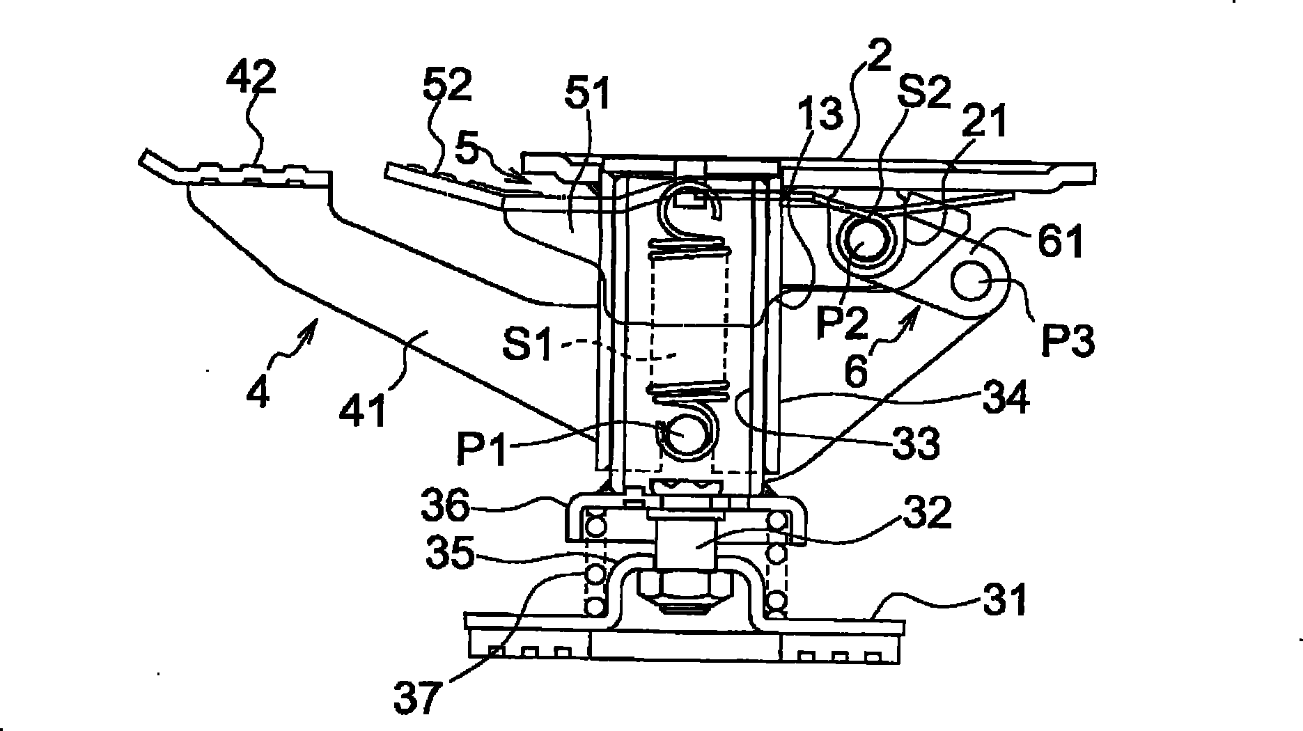
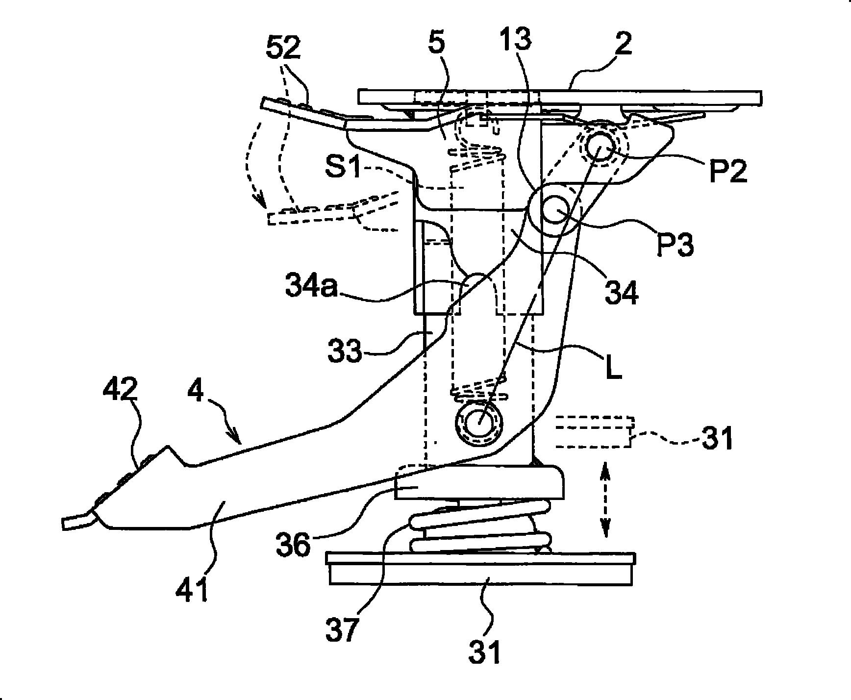
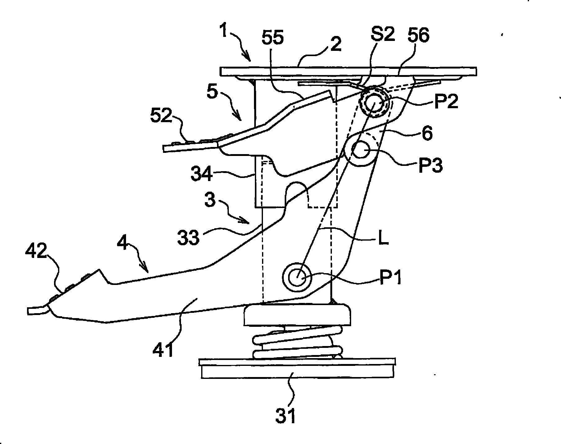
[0046] figure 1 and 2 The shown brake 1 includes: a plate-shaped support portion 2 at the upper end and a bracket portion 3 that is biased upward and can be stretched, a locking pedal lever 4 hinged on the bracket portion 3, and arranged side by side on the locking pedal lever 4 The outer side and rear end side of the lock release pedal lever 5 hinged inside the support part 2, and the connecting piece 6 bridged between the front end of the lock pedal lever 4 and the back of the support part 2 and hinged.

[0047] In addition, in this embodiment, the left side in the figure is taken as the front, and the right side is taken as the rear.

[0048] [stand part]

[0049] The stand portion 3 is composed of a movable portion and a non-movable body portion. The main body part is composed of a base part 31 , a leg part 32 erected on the base part 31 , and an inner cylinder part 33 supported by the leg part 32 .

[0050] The movable portion is constituted by an outer cylinder porti...


PUM


Abstract

The present invention relates to a safe and reliable earth brake of which the fixing pedal rod and fixing releasing fixing pedal rod are not crossed. Even the finger or article, etc. enters the space between the fixing pedal rod and the fixing releasing fixing pedal, the finger or article is not clamped with strong force. The earth brake comprises the following components: a bracket part which isprovided with a plate-shaped support part at the upper end and is offset upwards and is elastic; the fixing pedal rod which has an approximate V-shape and is articulated on the bracket part by a first pin and simultaneously gets across the bracket part extending frontwards and backwards; a fixing releasing pedal rod which is parallely installed at the outside of fixing pedal rod and has a back side that is articulated inside the supporting part through a second pin; and a connecting sheet which is positioned between the second pin and the fixing pin. The back side of fixing pedal rod is installed with a fixing pin which can engage with the bracket part, and the front side is installed with a pedal part.

Description

technical field [0001] The present invention relates to an improvement of a floor brake for fixing a wheelbarrow equipped with a wheel portion such as casters at a desired position. Background technique [0002] In the past, the ground brake, for example, as shown in No. 53-52767, includes: a cylindrical bracket; a pressure rod lifting body that can be lifted coaxially with respect to the cylindrical bracket; A compression spring that biases the lifting body of the pressing rod upward; a shaft protruding outward from the shaft end that is arranged transversely to the above-mentioned bracket; a locking pedal rod that is freely swingably connected around the above-mentioned shaft, and has a The pedal part has the first pin parallel to the above-mentioned axis at the other end, and also includes a ㄑ-shaped arm formed between the above-mentioned pedal part and the first pin; The second pin is arranged parallel to the first pin through the bearing receiving piece at the bottom; ...

Claims


Application Information

Patent Timeline
Patent Type & Authority Patents(China)
IPC IPC(8): B62B5/04B62B9/08
CPCB62B5/049B62B5/0433
Inventor 三浦裕昭横堀刚宏
Owner NANSIN CO LTD
Why Eureka
Try Eureka