Cable side electric connector

An electrical connector and connector technology, applied in the direction of connection, parts and circuits of connecting devices, can solve the problems of difficulty in ensuring elasticity, small deflection and displacement, and high rigidity, and achieve an increase in the number of parts, easy locking, The effect of large displacement

Inactive Publication Date: 2009-07-01
HIROSE ELECTRIC GROUP
View PDF1 Cites 2 Cited by
  • Summary
  • Abstract
  • Description
  • Claims
  • Application Information

AI Technical Summary

Problems solved by technology

Therefore, the cable connected to the connector also extends in a direction parallel to the circuit board and is limited within the height dimension of the connector.
Although the connector of Patent Document 1 is also required to be thinner, since the connector is fitted in the height direction of the connector, the above-mentioned locking piece extending in this direction and having a protrusion on its front end side can only hold the height of the connector. The hei

Method used


Image

  • Cable side electric connector
  • Cable side electric connector
  • Cable side electric connector

Examples


Embodiment Construction

[0032] An embodiment of the present invention will be described below with reference to the drawings.

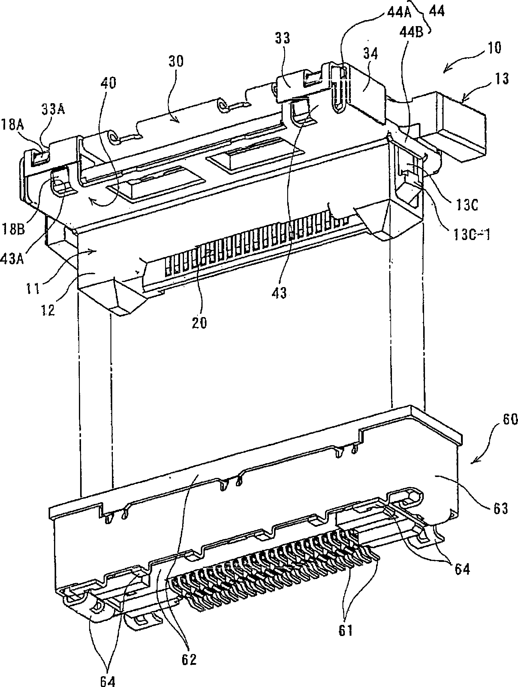
[0033] figure 1 It is a state before fitting the connector 10 of this embodiment and the mating connector 60, and is an overall perspective view seen from below. In this figure, the circuit board mounted at the bottom surface side of the object connector 60 is omitted.

[0034] On the object connector 60, an L-shaped connection portion 61 extending from the bottom surface of a plurality of terminals, when the object connector 60 is arranged on a circuit board (not shown), the connection portion 61 and the corresponding circuit of the circuit board welding. The object connector 60 is equipped with a metal case 63 for shielding on the peripheral surface of the housing 62 used to hold the above-mentioned terminals, and an L-shaped fixing foot 64 extends from the lower end of the metal case 63, and is fixed by welding. on the above circuit substrate. The mating connector 60 ...


PUM


Abstract

The present invention provides a cable side electric connector. A lever (13) is fixed to extend along the side surface of casing and have a wrist shape with flexibility. The cable side electric connector is provided with a transverse wrist part (13B) which extends from a supported end part (13A) that is supported by a casing (11) to a direction vertical to the inosculation direction of connector,namely the transverse direction, and a longitudinal wrist part (13C) which is changed with direction from the transverse wrist part to the inosculation direction of connector and extends to the longitudinal direction. The free end side of longitudinal wrist part is provided with a fixing part (13C-1) which is clipped with the objective connector. The connection part (13E) between the transverse wrist part and the longitudinal wrist part, or the transverse wrist part, or the extension part which extends from the connection part or the longitudinal wrist part to the end of supported end is provided with a pressed part (13D) which is pressed in the direction for realeasing the fixing and shifts. The invention can sufficiently ensure the flexture amount of lever in fixing.

Description

【Technical field】 [0001] The present invention relates to a cable-side electrical connector, in particular to an object connector that is fitted onto the circuit substrate from a direction perpendicular to the surface of the circuit substrate, and the connected cable is extended to be parallel to the surface of the circuit substrate. device. 【Background technique】 [0002] Such a connector is disclosed in Patent Document 1. This known connector is equipped with a metal case which covers the upper surface opposite to the mounting surface of the circuit board for shielding. The metal cover is also bent toward the side of the connector, and has a foot-shaped locking piece parallel to the side and extending toward the surface of the circuit board. The protrusions for locking and locking between devices (refer to Patent Document 1, figure 1 ). [0003] 【Patent Document 1】 [0004] Japanese patent application 2006-244732 [0005] In order to miniaturize electronic equipment ...

Claims


Application Information

Patent Timeline
IPC IPC(8): H01R13/639H01R13/658
CPCH01R12/772H01R12/79H01R13/629
Inventor 山口英统涉谷敏夫
Owner HIROSE ELECTRIC GROUP
Why Eureka
Try Eureka