

Contact box for switch cabinet
A contact box and switch cabinet technology is applied in the field of contact boxes to achieve the effects of avoiding corona, eliminating air gaps, and eliminating the phenomenon of gap discharge.
Active Publication Date: 2010-12-01
浙江省开化七一电力器材有限责任公司
View PDF0 Cites 1 Cited by
- Summary
- Abstract
- Description
- Claims
- Application Information
AI Technical Summary
Problems solved by technology
In order to overcome the above-mentioned problems existing in the prior art, the present invention aims to provide a contact box with a new structure for the switchgear. The contact box is not easy to produce corona phenomenon during the operation of the switchgear, which is beneficial to ensure that the contacts Insulation performance of the box, avoid breakdown phenomenon and prevent the occurrence of electrical accidents
Method used
View moreImage
Smart ImageViewing Examples

Examples
Embodiment Construction
Login to View More PUM
 Abstract
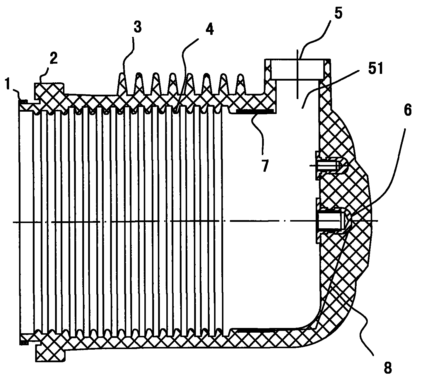
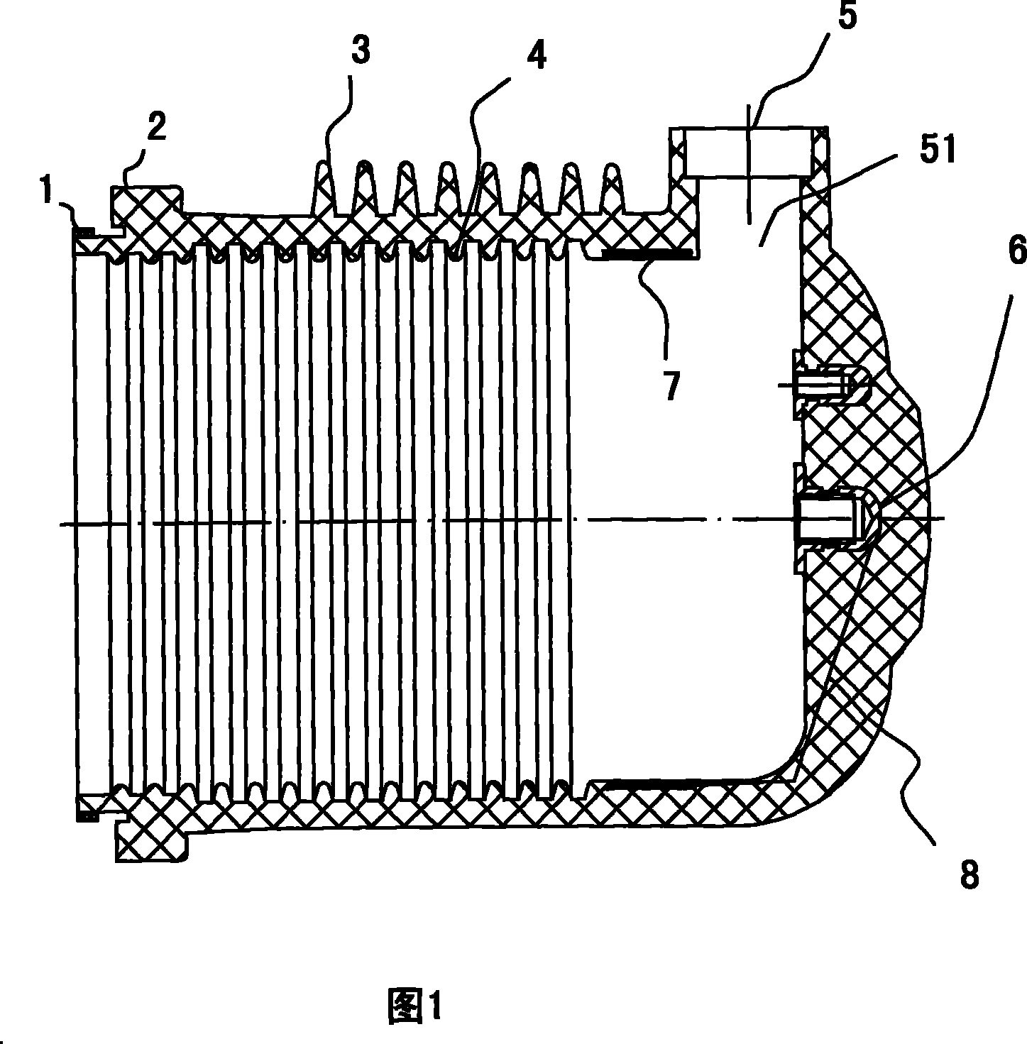
The invention provides a switch cabinet-used contact box, which comprises a tubular insulator with one open end and the other closed end. A bedplate joining opening is formed on the lower part of the tubular insulator. A continuous manager used for accommodating a busbar is arranged on the upper annular wall of the tubular insulator in the radial direction. The continuous manager is communicated with an intracavity. An embedded part for installing a stationary contact member is arranged at the top of the intracavity. The invention is characterized in that a silicone rubber ring is arranged onthe bedplate joining opening; a non-magnetic metal cylindrical shielding layer is arranged on the inner wall of the intracavity of the tubular insulator below the continuous manager; the non-magneticmetal cylindrical shielding layer is connected with the embedded part for installing the stationary contact member through a conducting wire. The product eliminates the phenomena that as an air gap exists between the stationary contact member and the inner wall of the contact box, discharge is initiated easily, and continuous coronae is generated; the curvature radius is increased so that electrical field energy is distributed along the shielding layer, thereby enabling uniform electric fields to be formed. In addition, the silicone rubber ring is favorable for eliminating the air gap betweenthe contact box and a joining holder thereof, thereby eliminating the gap discharge phenomenon.
Description
Contact box for switchgear 【Technical field】 The invention belongs to an accessory used with electric equipment, in particular to a contact box matched with an AMS-24 switch cabinet. 【Background technique】 The existing contact box used in conjunction with AMS-24 switchgear, its structure includes a cylindrical insulator formed by epoxy compound with one end open and the other end closed, and a static contact installation insert is provided on the top of the inner wall of the insulator. The inner and outer walls are provided with skirts. There is a through groove on the ring wall of the upper part of the insulator, and the through groove is used to receive the busbar, so that the busbar radially extends into the inner cavity of the insulator through the through groove, and is connected with the static contact through the installation insert. The contact box with this structure has the following problems in practical application: the electric field is not uniform, and there...
Claims
Login to View More Application Information
Patent Timeline
 Patent Type & AuthorityPatents(China)
IPC IPC(8): H02B1/14
Inventor操隆震应兵荣余红英赵侃方蕾
Owner浙江省开化七一电力器材有限责任公司