Electro-optical sampling method based on polarization rotation effect of semiconductor optical amplifier
An optical amplifier and electro-optic sampling technology, applied in the field of optoelectronics, can solve problems such as unfavorable optical signal processing, not in line with the development direction of optical device integration, high loss, etc.
- Summary
- Abstract
- Description
- Claims
- Application Information
AI Technical Summary
Problems solved by technology
Method used
Image
Examples
Embodiment Construction
[0039]Step 1 Composition of electro-optic sampling system
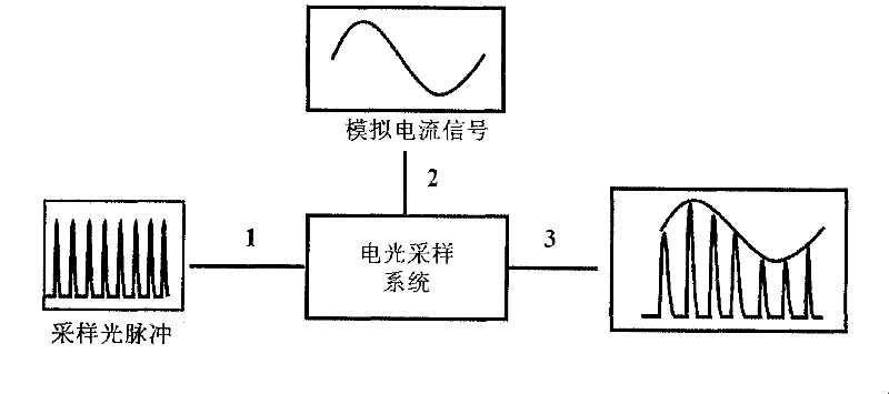
[0040] Such as figure 2 As shown, the electro-optic sampling system is composed of an input optical fiber 1, a first polarization controller 4, a semiconductor optical amplifier (SOA) 5, a second polarization controller 6, a polarization beam combiner 7 and an output optical fiber 3 through optical connections in sequence;
[0041] Step 2 Determination of optical working parameters
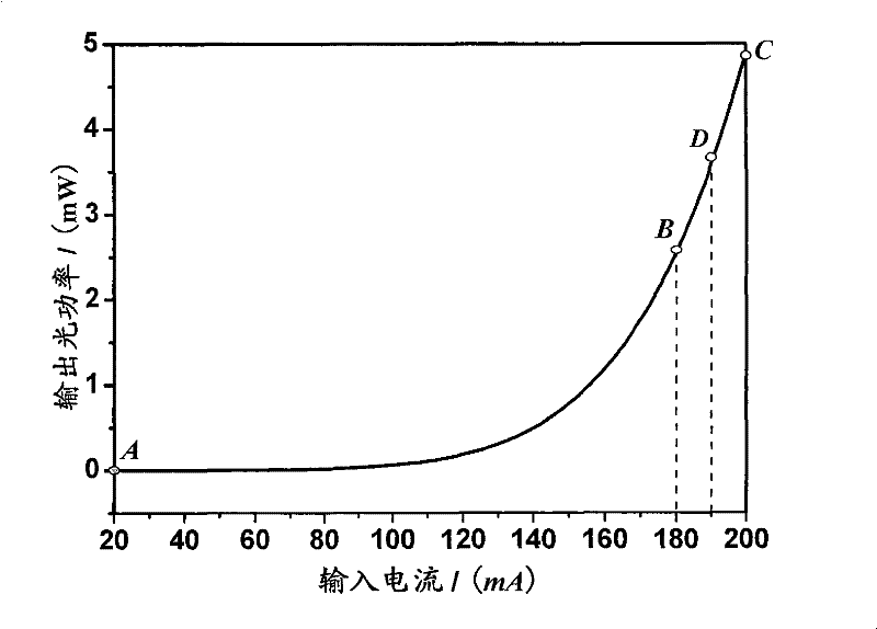
[0042] Step 2a: Determine the minimum value of 20mA and the maximum value of 200mA for the input current intensity of SOA from the technical description document of SOA 5;
[0043] Step 2b: Input a current with a strength of 20mA at the electrical input port of the SOA 5, input a continuous light with an optical power P of -15dBm into the input optical fiber 2, and measure the optical power at the output end of the output optical fiber 3;
[0044] Step 2c: Calculate the angle θ between the polarization direction of the first polarizati...
PUM
 Abstract
Description
Claims
Application Information
 - R&D
- Intellectual Property
- Life Sciences
- Materials
- Tech Scout
- Unparalleled Data Quality
- Higher Quality Content
- 60% Fewer Hallucinations
Browse by: Latest US Patents, China's latest patents, Technical Efficacy Thesaurus, Application Domain, Technology Topic, Popular Technical Reports.
© 2025 PatSnap. All rights reserved.Legal|Privacy policy|Modern Slavery Act Transparency Statement|Sitemap|About US| Contact US: help@patsnap.com


