
Data retransmitting method, network control device, mobile station and base station

A technology for data retransmission and network control, applied in the fields of data retransmission, mobile stations, base stations, and network control devices, can solve the problems of lost data, discarding, useless retransmission, etc., achieve rapid handover, reduce data volume, and prevent throughput volume reduction effect

Inactive Publication Date: 2009-08-12
MITSUBISHI ELECTRIC CORP
View PDF1 Cites 5 Cited by
  • Summary
  • Abstract
  • Description
  • Claims
  • Application Information

AI Technical Summary

Problems solved by technology

Therefore, there is a problem that the data after receiving NACK or the data after receiving any of the ACK / NACK, and the data that has received the ACK (data that has been sent) also becomes the object of retransmission, and will A useless retransmission occurs
In particular, under the conditions (RLCAM) where the existing data retransmission method is applicable, retransmission control is performed using the Selective Repeat ARQ method that transmits a plurality of data within the transmission window at one time without confirming the delivery of the previous data. , according to the existing data retransmission method, when only the data with the earlier sequence number in the sending window does not receive the ACK, and most of the data sent after the data receive the ACK, although most of the data in the sending window After receiving the ACK, almost all will be discarded and retransmitted
[0009] In addition, although the technology related to data retransmission when using RLC unacknowledged mode (UM: Unacknowledged Mode) and HARQ for data transmission for applications requiring real-time performance such as VoIP is not disclosed in the above-mentioned Patent Document 1, However, under "RLC UM", the RLC layer considers that the data has arrived at the receiving side at the moment of sending the data, so if switching is performed during HARQ-based retransmission in the MAC layer, data will be lost

Method used


Image

  • Data retransmitting method, network control device, mobile station and base station
  • Data retransmitting method, network control device, mobile station and base station
  • Data retransmitting method, network control device, mobile station and base station

Examples


Embodiment approach 1

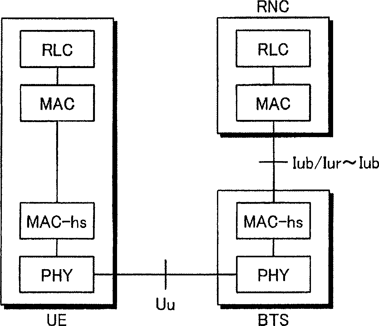
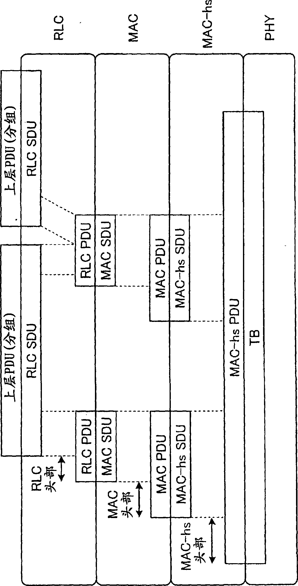
[0047] figure 1 It is a diagram showing an example of the protocol architecture for realizing the data retransmission method of the present invention. like figure 1 As shown, in this embodiment, the RLC layer and the MAC layer for processing downlink data transmission are configured in the RNC, and the MAC-hs layer is configured in the BTS. In addition, the RLC layer, the MAC layer and the MAC-hs layer are all configured in the UE to perform data reception processing. Connect by Iub interface between RNC and BTS, adopt the encapsulation method called frame protocol (FP, FrameProtocol) to forward the MAC data (recorded as MAC_PDU hereinafter) in RNC to BTS. Although not shown in the figure, the BTS may not be a BTS controlled by a Serving Radio Network Controller (SRNC, Serving RNC) as an RNC that performs UE call processing, but may be a drift radio network controller (SRNC) that is a different RNC. BTS controlled by DRNC, Drift RNC). In this case, user extension can be pe...

Embodiment approach 2

[0074] Next, Embodiment 2 will be described. In the above-mentioned Embodiment 1, the downlink data that needs to be retransmitted is forwarded (retransmitted) to the handover destination BTS when the handover is performed, but in this embodiment, it is explained that the UE determines the uplink data that needs to be retransmitted when the handover is performed, A data retransmission method for retransmitting the handover destination BTS after the handover is completed. Among them, the protocol architecture, protocol stack, and structure of the wireless communication system used to implement the data retransmission method in this embodiment are the same as those in Embodiment 1 above (refer to figure 1 , 2 , 3). In addition, in Embodiment 1, figure 1 with figure 2 The shown MAC-hs of the RNC and UE are processed as a MAC functional unit for downlink data, but in this embodiment, are processed as a MAC functional unit for uplink data.

[0075] The following is based on ...

Embodiment approach 3

[0089] Next, Embodiment 3 will be described. In Embodiments 1 and 2 above, the separation of the RLC layer and the MAC-hs layer on the network side enables high-speed and efficient handover in the protocol architectures of different devices such as the RNC and the BTS. On the other hand, in this embodiment mode, it is described as currently in 3GPP (3 rd The data retransmission method when the RNC and BTS are integrated such that the RLC layer and the MAC-hs layer (RLC part and MAC-hs part) on the network side are located in the same device as the 3.9th generation EUTRA and EUTRAN studied in the Generation Partnership Project .

[0090] Figure 17 It is a diagram of a configuration example of a wireless communication system that realizes the data retransmission method according to Embodiment 3. exist Figure 17 Among them, Evolved NodeB (ENB, Evolved NodeB) 6 and 7 are devices in which the RNC and BTS in Embodiment 1 are integrated, and have a MAC-hs part (MAC-hs part 21a...


PUM


Abstract

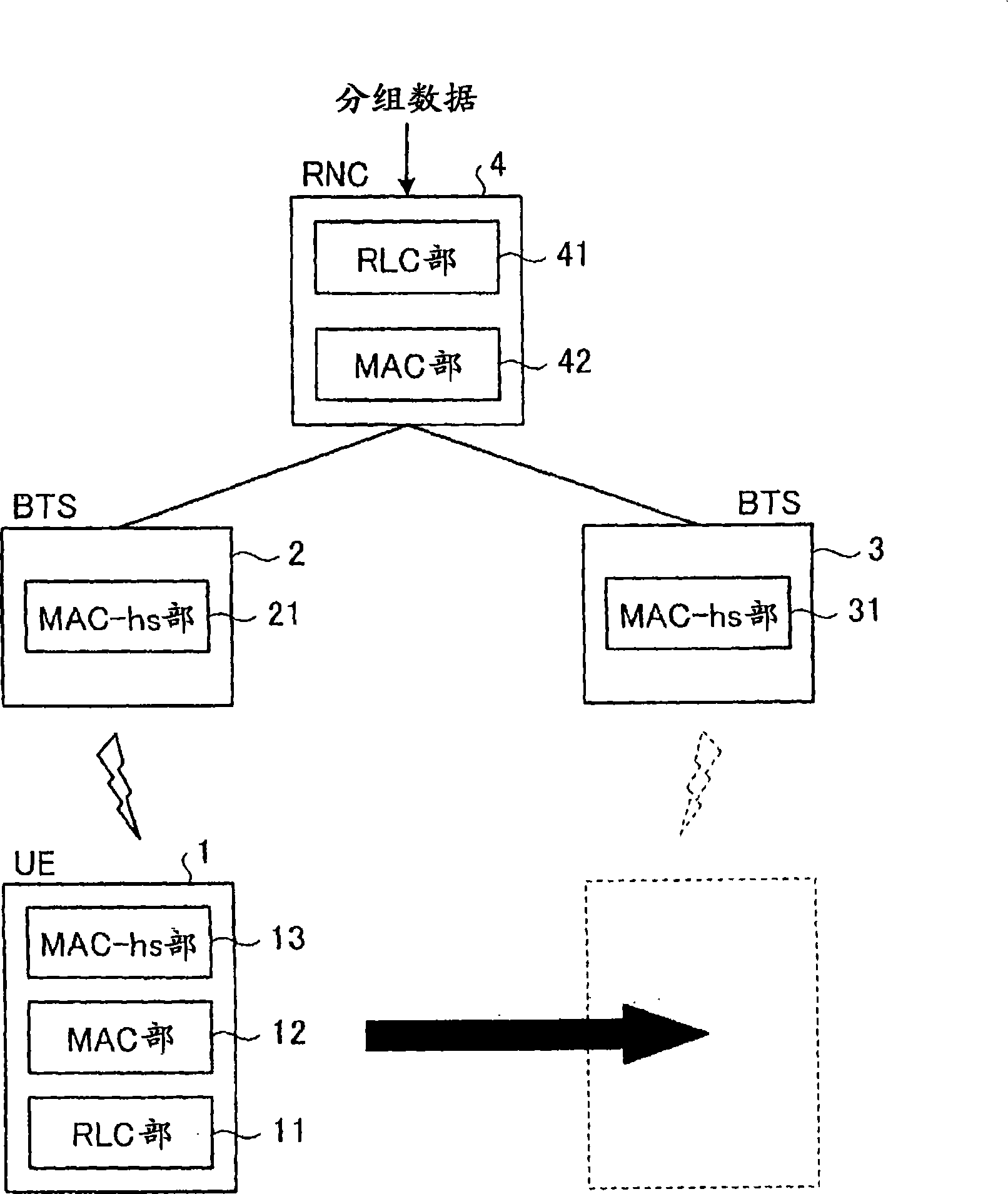
A data retransmitting method includes a packet transmitting step wherein an RNC (4) creates a packet of a desired size by using a data packet, and transmits the packet to a BTS (2) storing the destination UE (1) of the packet, in a wireless communication system; a reception result notifying step wherein the BTS (2) transmits the received packet to the UE (1), and the packet reception result obtained from the UE (1) is notified to the RNC (4); a data packet transmission result judging step wherein the RNC (4) judges, based on the reception result, whether the data packet that corresponds to the packet transmitted to the BTS (2) correctly reached the UE (1); and a data retransmitting step of retransmitting the data packet, which the RNC (4) judged not correctly reached the UE (1), through a handover destination BTS (3), in a case where the UE (1) performed handover.

Description

technical field [0001] The present invention relates to wireless communication technology, and in particular to retransmitting to a target mobile station data that may not reach the target mobile station due to handover execution in a wireless communication system composed of a mobile station and a base station with a retransmission control function A data retransmission method, a network control device, a mobile station and a base station for realizing the data retransmission method. Background technique [0002] Conventionally, High Speed ​​Downlink Packet Access (HSDPA, High Speed ​​Downlink Packet Access) and High Speed ​​Uplink Packet Access (HSUPA, High Speed ​​Uplink) have been standardized as methods for realizing high-speed packet transmission in the Universal Mobile Telecommunications Service (UMTS) system. PacketAccess). [0003] Among these methods, as the core technology for realizing high-speed packet transmission, it can be listed: high-speed packet sending a...

Claims


Application Information

Patent Timeline
Patent Type & Authority Applications(China)
IPC IPC(8): H04W28/04H04W36/02H04W36/08
CPCH04L2001/0092H04L1/1874H04W28/04
Inventor 前田昌也
Owner MITSUBISHI ELECTRIC CORP
Learn More