

Electric-controlled micro valve implemented by shape memory alloy
A technology of memory alloy and electronic control, which is applied in the direction of lifting valve, valve detail, multi-way valve, etc., can solve the problems of difficult modification and complex structure, and achieve the effect of small size, reduced volume and weight, and easy manufacturing and production
Inactive Publication Date: 2010-12-01
TONGJI UNIV
View PDF0 Cites 0 Cited by
- Summary
- Abstract
- Description
- Claims
- Application Information
AI Technical Summary
Problems solved by technology
However, this traditional valve is difficult to meet these needs because of its precise structure and complex structure, and it is not easy to be refitted.
Method used
View moreImage
Smart ImageViewing Examples


Examples
specific Embodiment approach 1
specific Embodiment approach 2
Embodiment approach
Login to View More PUM
 Abstract
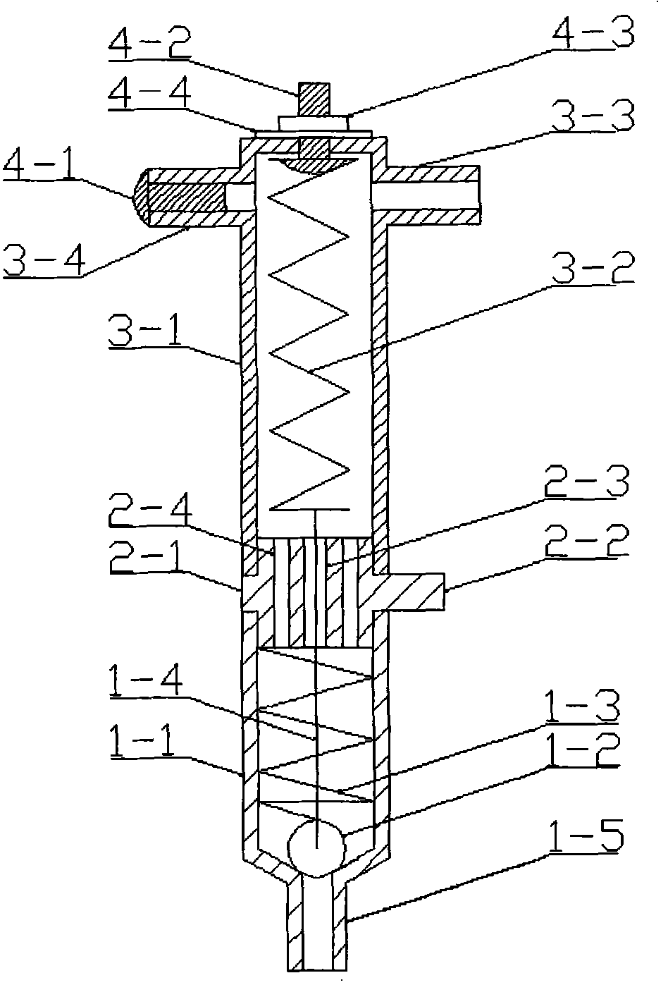
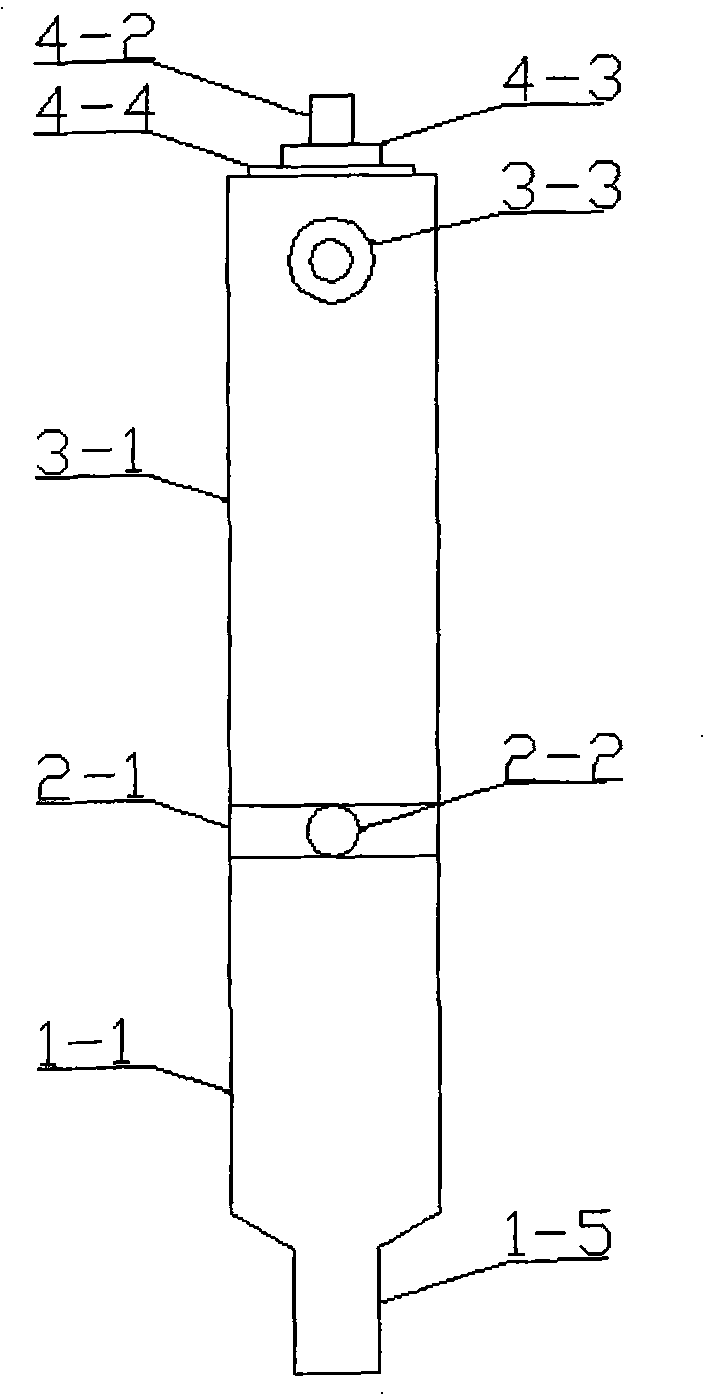
An electronic control micro valve realized by shape memory alloy comprises a liquid inlet tube, a spacer layer, a sparge pipe, a shape memory alloy drive, a linkage piece, a valve ball and a bias pressure spring; wherein, the liquid inlet tube and the sparge pipe are connected by being respectively connected and fixed with the spacer layer; the valve ball is positioned in the sparge pipe and is over against a jet pipe; one side of the valve ball far away from the jet pipe is connected with the linkage piece; the other end of the linkage piece is connected with the shape memory alloy drive by passing through the spacer layer; the other end of the shape memory alloy drive is fixed at the top of the liquid inlet tube; one end of the bias pressure spring is against the spacer layer and the other end thereof is connected with the valve ball; under certain pressure state, the bias pressure spring presses the valve ball against the jet pipe to cause the jet pipe to close; the electric energycontrols the shape memory alloy drive to act to drive the valve ball to further open and close the valve. The micro valve has low manufacturing cost, small volume, light weight, simple structure and simple and convenient assembly and disassembly and is easily suitable for certain specific industry and agriculture and life automation requirements by improving structures.
Description
Electronically Controlled Micro-valve Realized by Shape Memory Alloy technical field The invention relates to a controllable valve element device, in particular to an electric energy control valve realized by shape memory alloy. Background technique Traditional micro valves are usually controlled electromagnetically. This kind of micro-valve realizes the opening and closing of the valve through the magnetic force generated by the electromagnetic coil to drive the valve core and the clutch valve port. Usually this kind of valve has high cost, small flow coefficient, and is easily damaged by voltage shock. Moreover, its control voltage is usually 12V or 24V and above, which is not suitable for some applications that require a lower voltage drive. In addition, in some practical application scenarios, it is necessary to use the valve for some specific signal output to precisely control the flow of water to meet the needs of automatic control. However, this traditional valve...
Claims
Login to View More Application Information
Patent Timeline
 Patent Type & AuthorityPatents(China)
IPC IPC(8): F16K1/14F16K31/64F16K11/044
Inventor何斌刘振黎明和
OwnerTONGJI UNIV