Check patentability & draft patents in minutes with Patsnap Eureka AI!

Rotary cutting method of foaming sponge

A foaming sponge and sponge technology, applied in the direction of shearing devices, shearing machine control devices, metal processing equipment, etc., can solve problems such as poor index values, large fluctuations in physical properties, and large differences in the structure of sponge longitudinal pores

Active Publication Date: 2009-08-26
CHANGDE LYRUN MATERIAL
View PDF0 Cites 0 Cited by
  • Summary
  • Abstract
  • Description
  • Claims
  • Application Information

AI Technical Summary

Problems solved by technology

At present, the slicing process of the sponge is generally to slice the massive sponge body into sheets of required thickness. The rotary cutting method is: along the direction ("horizontal direction") parallel to the moving direction axis of the sponge body. During the foaming process of the sponge, the pores at the bottom of the foam body are larger than the pores at the top, and because of continuous foaming, the direction of the pores is slightly inclined to the end of the foam body, and the structure of the longitudinal pores of the sponge is quite different. The cutting method makes the pore distribution of the flaky sponge after rotary cutting very uneven, and the shape of the holes in each part is greatly different, which leads to the phenomenon of light and dark interlacing (stripes) in the porous sponge metal made of this flaky sponge, and its physical properties Large performance fluctuations and poor index values

Method used


Image

  • Rotary cutting method of foaming sponge
  • Rotary cutting method of foaming sponge
  • Rotary cutting method of foaming sponge

Examples


Embodiment 1

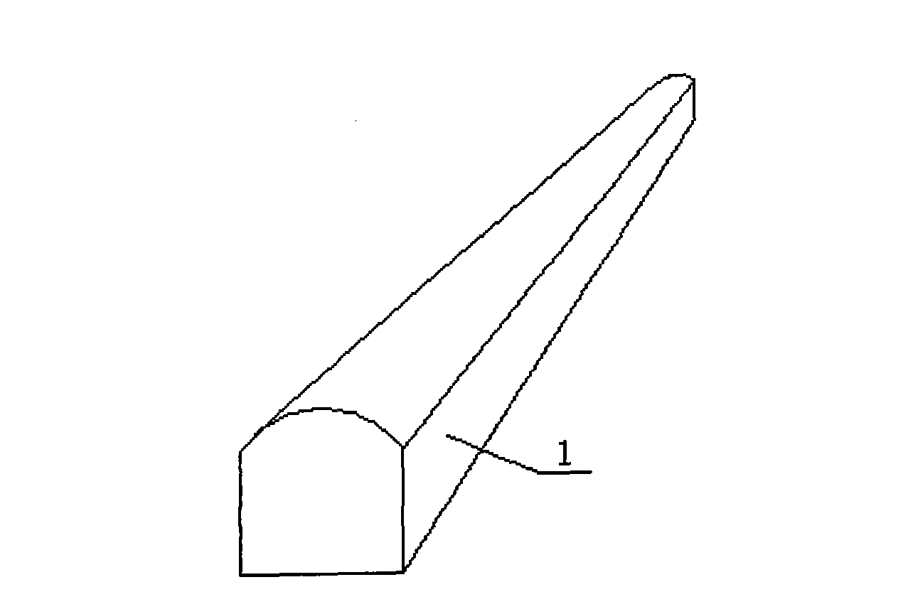
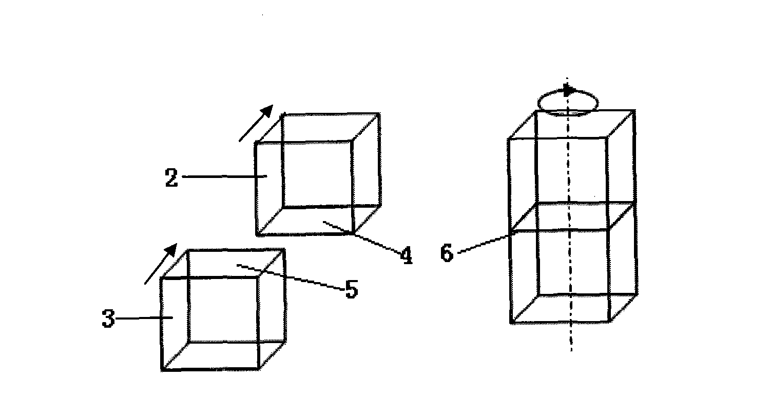
[0013] Refer to figure 1 , (1) Cut the top and bottom of the sponge body 1 to a thickness of 20cm; (2) Cut at least 2 pieces of the sponge body with the top and bottom away along the direction of movement of the foam body (Note: figure 1 The straight arrow in the middle indicates the direction of movement of the foam body) The vertical upper and lower surfaces are bonded, see the bonding process figure 2 , The bonding interface 6, is formed by the bottom surface 4 of one foam body 2 on the top surface 5 of the other foam body 3; (3) along the vertical axis ( figure 2 The dotted line shows the upper and lower axis) parallel to the direction of the rotary cut into a sheet of sponge ( figure 2 The direction of the middle rotating arrow indicates the direction of rotary cutting, and the straight arrow indicates the direction of bubble movement, that is, the upper and lower axis perpendicular to the direction of bubble movement is the central axis of rotary cutting).

[0014] Perf...

Embodiment 2

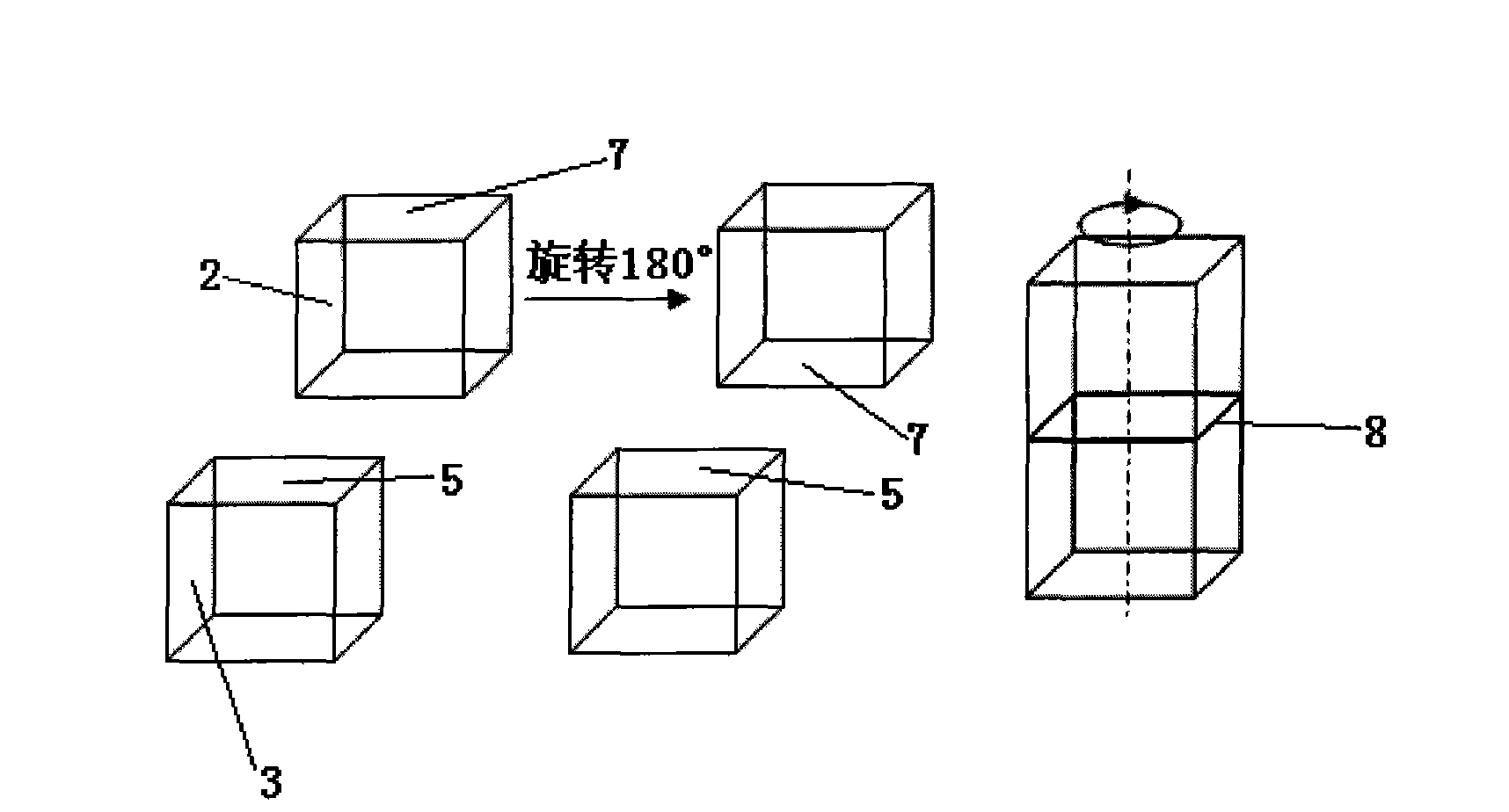
[0022] (1) Cut off the convex part and the bottom of the sponge foam body 1 to a thickness of 15 cm; (2) At least 2 pieces of the foam body) 2 and 3 are bonded along the upper and lower surfaces perpendicular to the direction of movement of the foam body ( See image 3 ), the bonded interface 8 is formed by the top surfaces 7 and 5 of the two foam bodies facing each other, that is, the foam body 2 is rotated 180° so that the top surface 7 is opposite to the top surface 5 of the foam body 3; (3) Then along the vertical axis ( image 3 The dotted line shows the upper and lower axis) parallel to the direction of the rotary cut into a sheet of sponge ( image 3 The direction of the middle rotating arrow indicates the direction of rotary cutting, and the straight arrow indicates the direction of bubble movement, that is, the upper and lower axis perpendicular to the direction of bubble movement is the central axis of rotary cutting).

Embodiment 3

[0024] (1) Cut off the convex part and bottom surface of the sponge foam body 1 by 25cm; (2) Then at least two pieces of the foam body 2 and 3 are bonded along the upper and lower surfaces, and the bonding interface is composed of two bubbles The bottom surface of the body is formed oppositely, that is, the foam body 3 is rotated 180° so that the bottom surface is opposite to the bottom surface of the foam body 2; (3) Then, it is cut into slices along the direction parallel to the vertical axis perpendicular to the movement direction of the foam body. Sponge (upper and lower axis perpendicular to the direction of bubble movement is the central axis of the rotary cutting).


PUM


Abstract

The invention provides a rotary cutting method of foaming sponge. The method comprises the following steps: (1) cutting top convex part and bottom of the foaming sponge with thickness of the cut part being 10-30cm; (2) bonding at least two pieces of the foaming sponge with top convex part and bottom thereof cut along top and bottom interfaces which are vertical to moving direction of the foaming body; and (3) rotarily cutting the sponge into sponge pieces along the direction parallel to the upper and lower axes. The method can help cut the sponge into sponge pieces with even hole distribution and uniform hole form, dark and light interlaced stripe phenomena of the porous sponge metal made from the sponge pieces obviously disappears, fluctuation of physical property of the product is small, and all technical indexes are good.

Description

Technical field [0001] The invention relates to a peeling method of foamed sponge. Background technique [0002] In the manufacturing process of porous sponge metal, sheet sponge is used as a carrier for metal deposition. The pore uniformity and pore shape of the sponge itself directly affect the uniformity of metal deposition on its surface and affect the final product. The main physical properties. At present, the sponge slicing process is generally to cut the block sponge into a sheet of the required thickness. The rotary cutting method is: peeling along the direction parallel to the moving direction axis of the sponge ("horizontal direction"), but In the foaming process of the sponge, the pores at the bottom of the foam have a larger pore diameter than the top pores, and because it is continuously foamed, the direction of the pores is slightly inclined to the end of the foam, and the longitudinal pore structure of the sponge is quite different. Therefore, the horizontal rotat...

Claims


Application Information

Patent Timeline
Patent Type & Authority Applications(China)
IPC IPC(8): B23D36/00
Inventor 谢红雨李星朱济群龙文贵胡鹏肖腾彬段志明刘珍萍刘新夏健康
Owner CHANGDE LYRUN MATERIAL
Features
  • R&D
  • Intellectual Property
  • Life Sciences
  • Materials
  • Tech Scout
  • Unparalleled Data Quality
  • Higher Quality Content
  • 60% Fewer Hallucinations
Learn More