Pressure sensor

A pressure sensor and pressure technology, applied in the direction of measuring fluid pressure, instruments, measuring fluid pressure through electromagnetic components, etc., can solve the problems of complicated installation and operation, increasing the size of the pressure sensor, increasing the size and weight, etc.

Inactive Publication Date: 2009-08-26
PANASONIC CORP
View PDF10 Cites 12 Cited by
  • Summary
  • Abstract
  • Description
  • Claims
  • Application Information

AI Technical Summary

Problems solved by technology

[0004] However, the conventional pressure sensor has such a problem that because it includes a glass base, the size and weight increase accordingly
[0005] Since the sensor chip is mounted by wire bonding, there is a problem of complicating the mounting operation, and it becomes necessary to form a space for performing the wire bonding, so that the size of the pressure sensor is increased.

Method used


Image

  • Pressure sensor
  • Pressure sensor
  • Pressure sensor

Examples


Embodiment Construction

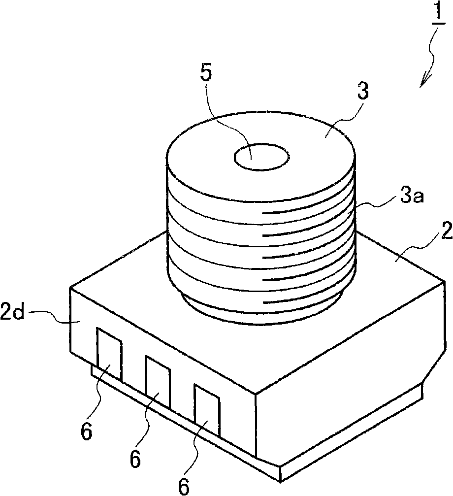
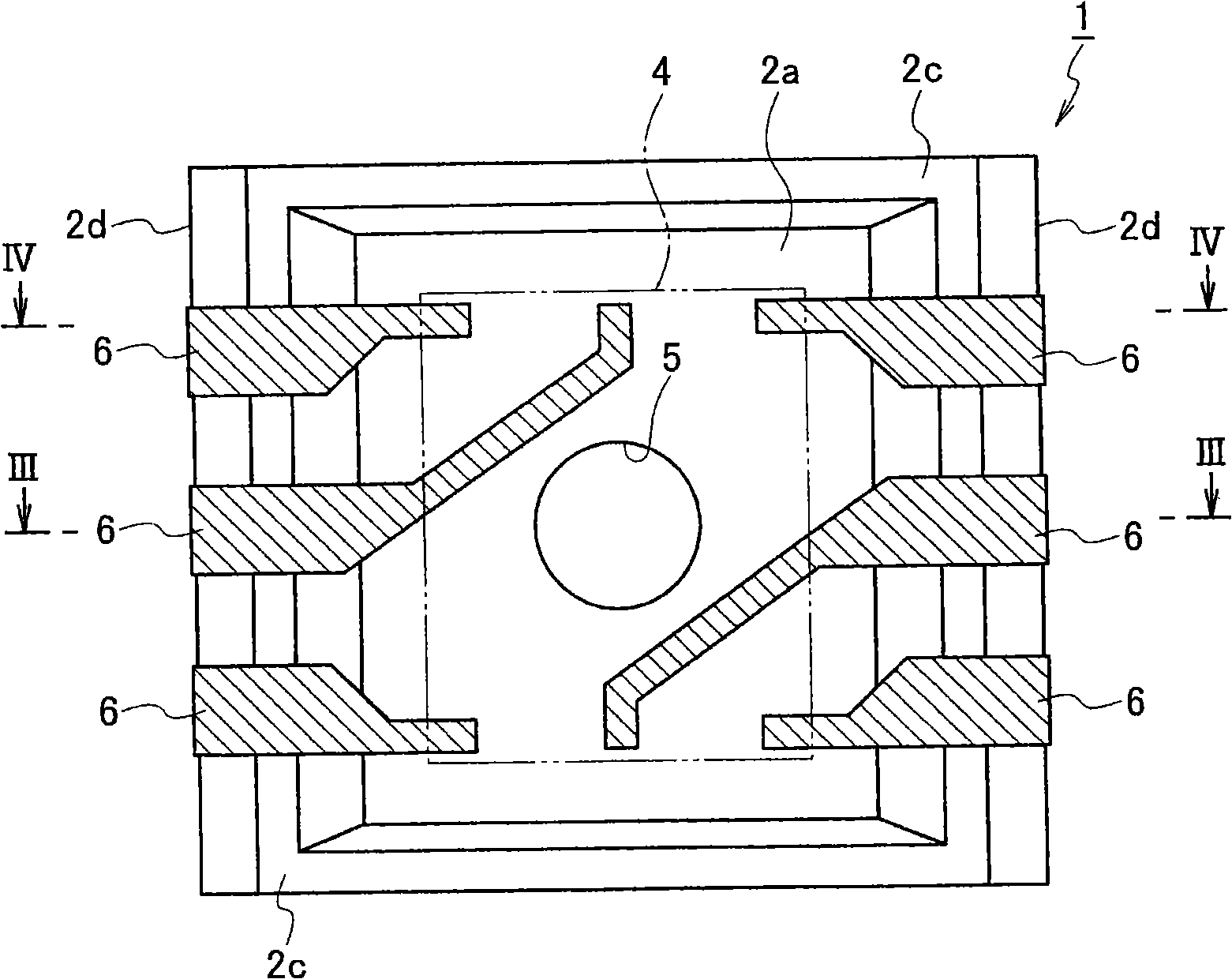
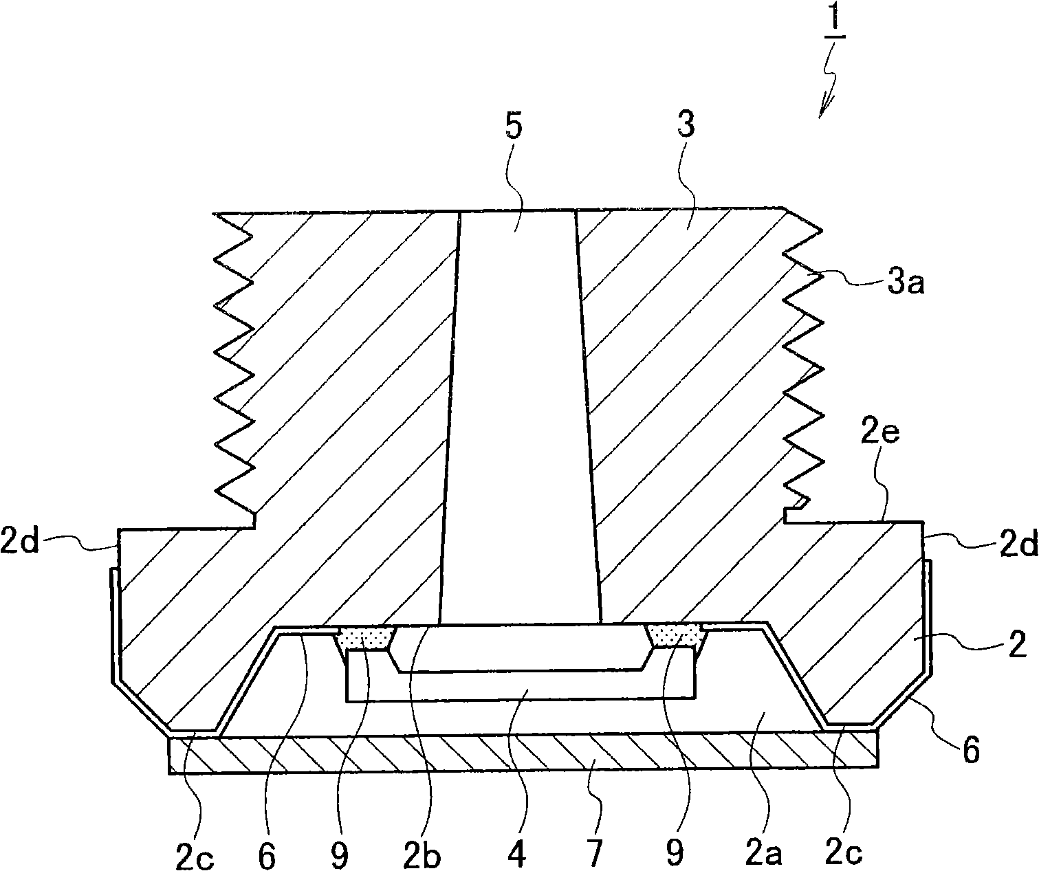
[0042] (first embodiment) figure 1 is a perspective view of a pressure sensor according to a first embodiment of the present invention, figure 2 is a plan view of the pressure sensor viewed from its rear side (the side opposite to the detection side of the pressure detection element), image 3 is along figure 2 A cross-sectional view of line III-III in, Figure 4 is along figure 2 A sectional view of line IV-IV in, Figure 5 is a plan view of the pressure sensor when viewed from its rear side and showing the sealing area where the sealant seals the pressure sensing element, Image 6 It is a side view showing the state where the pressure sensor is mounted.

[0043] A pressure sensor 1 according to an embodiment of the present invention includes a substantially cylindrical protrusion 3 provided on a flat surface (sealing surface) 2e of a base 2 having a substantially cuboid appearance. In this embodiment, the base portion 2 and the protrusion portion 3 correspond to the...


PUM


Abstract

In a pressure sensor 1 including a pressure detecting element 4 in an intermediate portion or at a deep side of a through hole 5 formed in a protrusion 3, a body portion (a base portion 2 and the protrusion 3) is made of ceramic or an insulative resin material and molded into a predetermined shape, and the pressure sensor is constituted as a molded interconnect device in which a conductive pattern 6 is formed on a surface thereof Accordingly, a smaller pressure sensor can be obtained.

Description

technical field [0001] The present invention relates to a pressure sensor for detecting fluid pressure. Background technique [0002] A conventional known pressure sensor having a sensor chip closes one end of a through hole formed in a package body as a pressure introduction hole (for example, Patent Document 1). [0003] According to the pressure sensor disclosed in Patent Document 1, the sensor chip is mounted on the resin package body through the glass base by wire bonding. In order to ensure the required detection accuracy, the glass base has the function of strengthening the package body to ensure the required detection accuracy of the sensor chip. [0004] However, the conventional pressure sensor has a problem that the size and weight increase accordingly because it includes a glass base. [0005] Since the sensor chip is mounted by wire bonding, there is a problem of complicating the mounting operation, and it becomes necessary to form a space for performing the w...

Claims


Application Information

Patent Timeline
Patent Type & Authority Applications(China)
IPC IPC(8): G01L9/00G01L9/06G01L9/08G01L9/12H01L29/84
Inventor 小林充井上浩牧永仁今井顺二正木康史池川直人中原阳一郎
Owner PANASONIC CORP
Why Eureka
Try Eureka