[0037] Specific implementation method
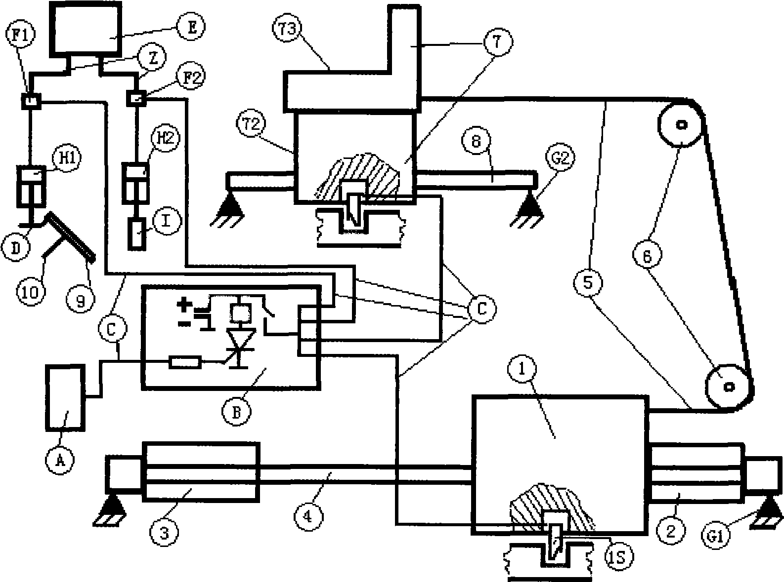
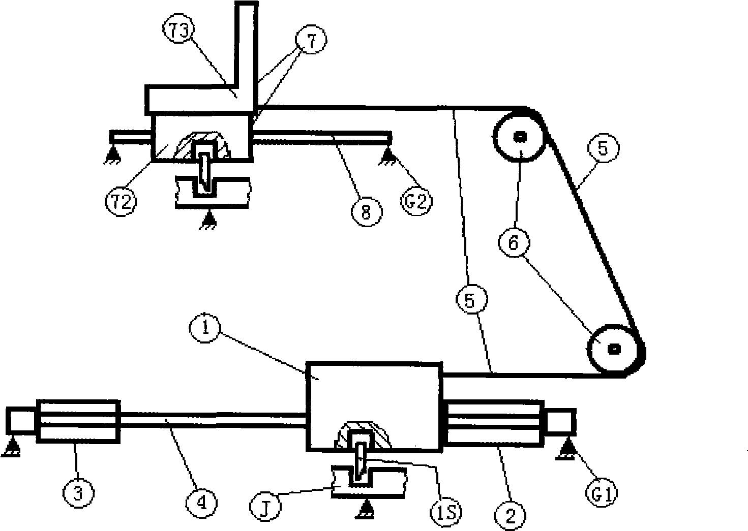
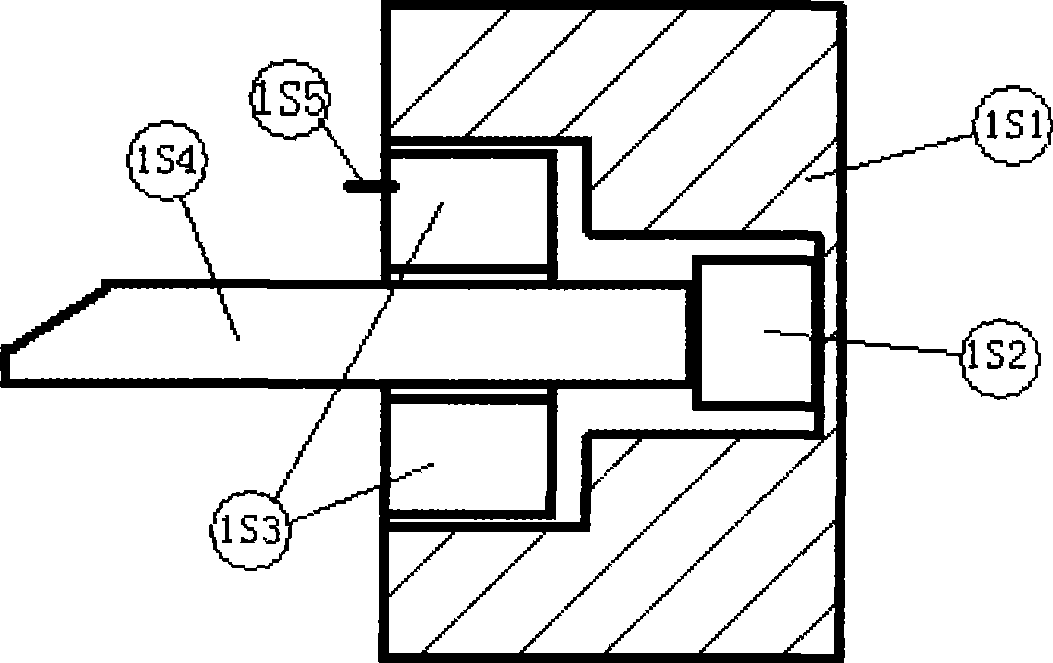
[0038]The device is composed of the vehicle's front seat rearward movement system, automatic braking system, automatic power stall system, control circuit system, collision degree detection system and connecting wires. It is characterized in that: the collision degree detection system A is connected to the control circuit through the connecting wire C The current-limiting starting resistor BR of system B is electrically connected, and the intermediate relay BMK output connecting wire C of control circuit system B is connected to the inertial kinetic energy weight 1 of the vehicle's front seat rearward movement system. The electromagnetic coil package 1S3 and the electromagnetic control lock of the electromagnetic control lock 1 The electromagnetic coil package 7S3 of the electromagnetic control lock in the rear-movable seat 7 is electrically connected. The output connecting wire C of the intermediate relay BMK of the control circuit system B is electrically connected with the electromagnetic coil F1 of the electromagnetic pneumatic valve in the automatic braking system. The output connecting wire C of the intermediate relay BMK of the control circuit system B is electrically connected with the solenoid F2 and the relay MK1 of the solenoid pressure valve in the automatic flameout system.
[0039] The rearward movement system of the front seat of the vehicle is composed of the inertial kinetic energy weight 1, the propulsion mechanism 2, the buffer energy absorption mechanism 3, the guide rail 4, the direction changing mechanism (the rope 5 and the rotating pulley 6), the rear movable seat 7, The seat rail 8, the grooved fixing part J, the chassis fixing part G1 and the frame fixing part G2 are composed. It is characterized in that the buffer energy absorption mechanism 3, the inertial kinetic energy weight 1 and the propulsion mechanism 2 are sequentially assembled on the guide rail 4 fixed to the chassis fixing part G1, and there is a space between the assembling buffer energy absorption mechanism 3 and the inertial kinetic energy weight 1 Moving distance, the inertial kinetic energy weight 1 and the propulsion mechanism 2 are close together. The inertial kinetic energy weight 1 is connected to one end of the rope 5 in the direction changing mechanism. The other end of the rope 5 is connected to the rear-movable seat 7 through a rotating pulley 6. The rear-movable seat 7 is installed on the seat rail 8 fixed to the frame fixing member G2. The inertial kinetic energy weight 1 and the rear-movable seat 7 are equipped with an electromagnetic control lock 1S (7S). The tongue of the electromagnetic control lock 1S (7S) is stuck in the groove of the grooved fixture J.
[0040] The automatic brake system is composed of a high-pressure air source E, an electromagnetic air valve F1, an air pressure propulsion column H1, a linkage link D, a brake pedal 9, an existing brake mechanism 10 and an air pressure connecting pipe Z. Its characteristic: The high-pressure air pressure source E is connected with the electromagnetic air pressure valve F1 through the air pressure connecting pipe Z. The electromagnetic pneumatic valve F1 is connected to the pneumatic propulsion column H1 through the pneumatic connecting pipe Z. The pneumatic propulsion column H1 is connected to the brake pedal 9 through a linkage link D. The brake pedal 9 keeps the original state with the existing original brake mechanism 10
[0041] The automatic power extinguishing system is composed of a high-pressure air pressure source E, an electromagnetic air pressure valve F2, an air pressure propulsion column H2, an existing flame extinguishing mechanism I, and an air pressure connecting pipe Z. It is characterized in that the high-pressure air pressure source E is connected to the electromagnetic air pressure valve F2 through the air pressure connecting pipe Z. The electromagnetic pneumatic valve F2 is connected to the pneumatic propulsion column H2 through the pneumatic connecting pipe Z. The connecting rod H23 of the pneumatic propulsion column H2 is connected with the existing flameout mechanism I. The existing flameout mechanism I remains the same.
[0042] The control circuit system is composed of power supply (vehicle power supply) BE, intermediate relay BMK, self-locking control tube (SCR) BT, current-limiting starting resistance BR, input connection line C1, output connection line C2 and grounding. Its characteristic is that the coil part of the intermediate relay BMK and the self-locking control tube BT are connected in series and connected in parallel with the power supply BE. One end of the normally open contact of the intermediate relay BMK is connected to the positive electrode of the power source BE, and the other end leads to the output connection line C2. One end of the current-limiting start resistor BR is connected to the control end of the self-locking control tube BT, and the other end leads to the input connection line C1. The negative pole of the power supply is grounded.
[0043] The collision degree detection system is connected in parallel by the normally open contacts of multiple travel switches A1, A2, A3... And it is installed in front of the front cross beam G12 of the vehicle chassis G1 or other reasonable positions.
[0044] When a car accident occurs, the material in front of the vehicle deforms backwards to the limit switches A1, A2, A3... in the detection system of the squeeze collision degree, so that one or more of them are closed, and the current passes through the current-limiting starting resistor BR The self-locking control tube (SCR) BT is turned on, the normally open contact of the intermediate relay BMK is closed, and the relay MK1 in the automatic flameout system, the solenoid F1 of the electromagnetic pressure valve in the automatic brake system, and the automatic flameout system The electromagnetic coil F21 of the electromagnetic air pressure valve, the electromagnetic coil package 1S1 of the electromagnetic control lock in the inertial kinetic energy weight and the electromagnetic coil package 7S3 of the electromagnetic control lock in the rear-movable seat act. Since the electromagnetic coil package 1S1 of the electromagnetic control lock in the inertial kinetic energy weight block and the electromagnetic coil package 7S3 of the electromagnetic control lock in the rear-movable seat act together, the inertial kinetic energy weight block 1 acts together with the propulsion force of the propulsion mechanism 2. The inertial kinetic energy weight 1 moves forward, and the rear seat 7 can be moved backward under the action of the direction changing mechanism (the rope 5 and the rotating pulley 6). At the same time, because the electromagnetic coil F1 of the electromagnetic pressure valve in the automatic brake system and the electromagnetic coil F2 of the electromagnetic pressure valve in the automatic flameout system act, the high-pressure gas in the high-pressure pressure source E passes through the electromagnetic pressure valves F1 and F2 to push the pressure into the columns H1 and H2. The piston in the pneumatic thrust column H1 advances forward to move the brake pedal 9 downward to make the existing original brake mechanism 10 perform a braking action. The piston in the pneumatic propulsion column H2 advances forward to make the existing flameout mechanism I perform a power flameout action. The action of the relay MK1 in the automatic flameout system causes the power to lose the power supply to maintain operation, and the power to flameout.
[0045] The variable speed ratio transmission mechanism is composed of two sliders 53 mounted on the guide rail 54 and an L-shaped telescopic lever 51 connecting the two sliders 53 and a lever fixed fulcrum 52. When the upper slider 531 (lower slider 532) is an active slider and moves from the left (right) to the right (left) at a constant speed, the upper force arm 511 will increase and the lower force arm 512 will shorten. The lower slider 532 of the driven slider moves at a reduced speed (the upper slider 531 moves at an accelerated speed).