
Wireless communication system and communication control method

A wireless communication system and wireless communication technology, applied in the field of wireless communication systems and communication control, can solve problems such as inability to start communication, failure of mobile station to receive, etc., and achieve the effect of avoiding receiving errors

Inactive Publication Date: 2012-03-07
KYOCERA CORP
View PDF5 Cites 0 Cited by
  • Summary
  • Abstract
  • Description
  • Claims
  • Application Information

AI Technical Summary

Problems solved by technology

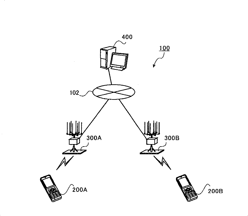
However, when there is an incoming call, if the base station transmits a signal using a modulation method that does not support the mobile station, the mobile station cannot receive the signal, and therefore cannot start communication.

Method used


Image

  • Wireless communication system and communication control method
  • Wireless communication system and communication control method
  • Wireless communication system and communication control method

Examples


no. 2 approach

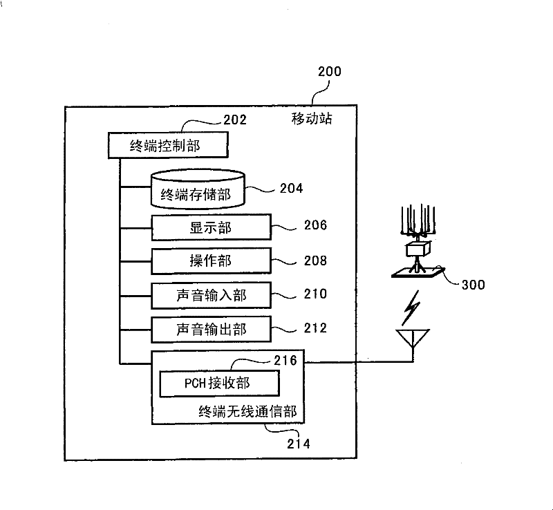
[0115] In the above-mentioned first embodiment, the structure in which the central server stores the identification information of the mobile station and the function information in correspondence is described, but the base station may also store the identification information of the mobile station in correspondence with the function information before an incoming call arrives. In the second embodiment, the configurations of the mobile station, the base station, and the center server will be described. In addition, the same code|symbol is attached|subjected to the structural element whose function is substantially the same as that of the said 1st Embodiment, and description is abbreviate|omitted.

[0116] (mobile station 250)

[0117] Figure 7 It is a functional block diagram showing the hardware configuration of the mobile station 250 according to this embodiment. Such as Figure 7 As shown, the mobile station 250 includes a terminal control unit 252 , a terminal storage ...


PUM


Abstract

The present invention provides a wireless communication system characterized in that a mobile station comprises a PCH receiving section, a base station comprises incoming call information receiving seThe present invention provides a wireless communication system characterized in that a mobile station comprises a PCH receiving section, a base station comprises incoming call information receiving section; a PCH generation section generating PCH by using modulation mode based received incoming call information; and a PCH sending section, a center server comprises: a server storage section storingction; a PCH generation section generating PCH by using modulation mode based received incoming call information; and a PCH sending section, a center server comprises: a server storage section storinglisted recognition information of a recognition mobile station and function information of the mobile station; a server extract section extracting function information from the server storage section listed recognition information of a recognition mobile station and function information of the mobile station; a server extract section extracting function information from the server storage section based on recognition information of the base station when call request to the mobile station exists; and a server sending section sending incoming call information containing the recognition informatbased on recognition information of the base station when call request to the mobile station exists; and a server sending section sending incoming call information containing the recognition information and extracted function information to the base station; the function information representing modulation mode corresponding to the mobile station. Therefore, modulation mode of mobile station of aion and extracted function information to the base station; the function information representing modulation mode corresponding to the mobile station. Therefore, modulation mode of mobile station of acquiring call target position, based on which, PCH receiving errors caused by different modulation modes are prevented.cquiring call target position, based on which, PCH receiving errors caused by different modulation modes are prevented.

Description

technical field [0001] The present invention relates to a wireless communication system and a communication control method. Background technique [0002] In recent years, mobile stations such as PHS (Personal Handy phone System) and mobile phones have been popularized, and improvements in communication quality and communication speed have been demanded in addition to miniaturization and weight reduction of mobile stations. For example, while maintaining communication quality, an adaptive modulation method that adaptively changes the modulation method according to changes in the communication environment to increase the communication speed is being used. Modulation methods with different bit rates are used as this modulation method, and BPSK (Binary Phase Shift Keying), QPSK (Quadrature PSK, quadrature phase shift keying) and QPSK (Quadrature PSK) are used sequentially from the modulation method with a low bit rate. phase keying), 16QAM (Quadrature Amplitude Modulation, quad...

Claims


Application Information

Patent Timeline
Patent Type & Authority Patents(China)
IPC IPC(8): H04W28/18H04W68/00
Inventor 星李佳
Owner KYOCERA CORP
Learn More