
Equipment

A device and node technology, applied in the electronic field, can solve problems such as clock signal delay time inconsistency, PMSYNC signal reception error, etc.

Active Publication Date: 2019-07-05
XFUSION DIGITAL TECH CO LTD
View PDF7 Cites 0 Cited by
  • Summary
  • Abstract
  • Description
  • Claims
  • Application Information

AI Technical Summary

Problems solved by technology

[0005] Based on the above processing method, the CPU in the slave node can only receive the clock signal and PMSYNC signal through multiple PMSYNC BUFFERs. Often multiple PMSYNC BUFFERs will cause transmission delays. In some cases, the delay time for the clock signal and the PMSYNC signal In this way, when the CPU of the slave node receives the PMSYNC signal according to the rising edge of the received clock signal, it will cause the rising edge of the clock signal to correspond to the transition edge of the PMSYNC signal, thus resulting in an error in receiving the PMSYNC signal

Method used


Image

  • Equipment
  • Equipment
  • Equipment

Examples


Embodiment Construction

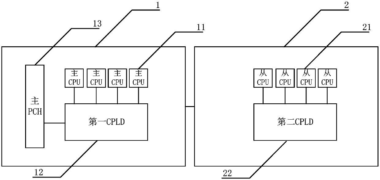
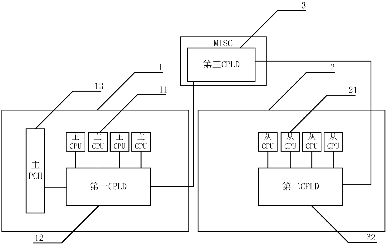
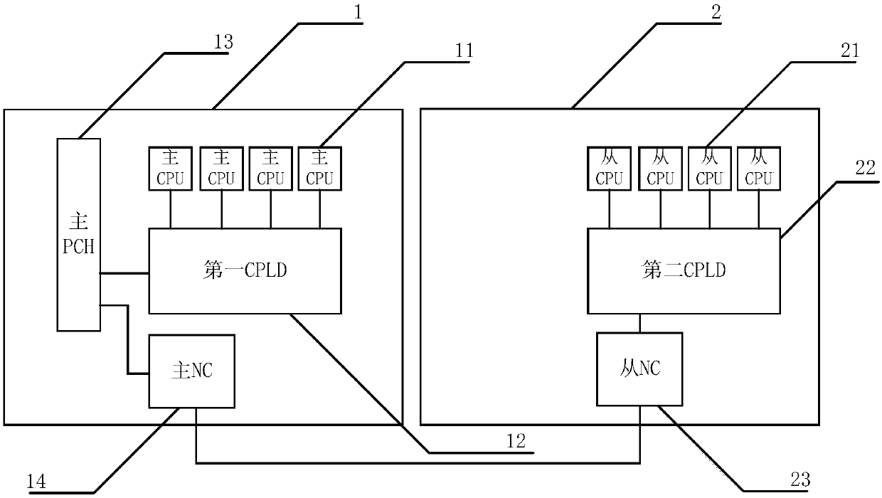
[0046] figure 1 It is a device provided by an embodiment of the present invention. see figure 1, the device may include a master node 1 and at least one slave node 2, the master node 1 includes four master CPU11, the first CPLD12, the master PCH13, each slave node 2 in at least one slave node includes four slave CPU21, the first Two CPLD22, wherein: the first CPLD12 is electrically connected with the main PCH13 and four main CPU11 respectively, and the second CPLD22 in each slave node 2 in at least one slave node is respectively electrically connected with four slave CPU21 in the corresponding slave node connection, the master node 1 is electrically connected to each slave node 2 in at least one slave node; the master PCH13 is used to generate the PMSYNC signal and the first clock signal, and send the PMSYNC signal and the first clock signal to the first CPLD12 The first CPLD12 is used to send the received PMSYNC signal and the first clock signal to four main CPU11; the seco...


PUM


Abstract

The embodiment of the invention discloses equipment, and belongs to the technical field of electronics. The equipment comprises a master node and at least one slave node, wherein the master node comprises four master CPUs, a master PCH and a first CPLD, each slave node comprises four slave CPUs and a second CPLD, the first CPLD is electrically connected with the master PCH and the four master CPUs, the second CPLD in each slave node is electrically connected with the four slave CPUs, and the master node is electrically connected with each slave node; the main PCH is used for generating a PMSYNC signal and a first clock signal and sending the PMSYNC signal and the first clock signal to the first CPLD; the first CPLD is used for sending the received PMSYNC signal and the first clock signal to the four main CPUs; the second CPLD is used for receiving the PMSYNC signal generated by the master PCH, obtaining a second clock signal, sending the second clock signal to the four slave CPUs, andsending the PMSYNC signal to the four slave CPUs when a first type of hopping edge of the second clock signal is detected; and the slave CPU is used for receiving the PMSYNC signal according to the second type of hopping edge of the second clock signal. According to the invention, the PMSYNC signal receiving error can be prevented.

Description

technical field [0001] The present application relates to the field of electronic technology, in particular to a device. Background technique [0002] At present, in order to increase the processing capability of the server, multiple nodes (such as two nodes) can be set in the server, wherein each node can include 4 central processing units (Central Processing Unit, CPU) and platform control unit (Platform Controller Hub, PCH). In addition, one of the nodes can be set as the master node, and the other nodes are slave nodes. In order to prevent the memory data from being lost when the server is powered off, the server is often equipped with a mechanism to save the memory data when the server is powered off. . [0003] Specifically, when a power failure is detected, the PCH of the master node can generate a state synchronization signal (PMSYNC signal) and a clock signal, which can be transparently transmitted to the 4 CPUs in the master node through the PMSYNC BUFFER in the...

Claims


Application Information

Patent Timeline
IPC IPC(8): G06F15/17G06F15/80
CPCG06F15/17G06F15/8038
Inventor 吴君和刘品强
Owner XFUSION DIGITAL TECH CO LTD
Learn More