Switchable joint constraint system

A technology of restraint systems and joints, applied in medical science, prostheses, sensors, etc., can solve the problem of depleting the motor ability of damaged limbs

Inactive Publication Date: 2009-09-02
KONINK PHILIPS ELECTRONICS NV
View PDF1 Cites 4 Cited by
  • Summary
  • Abstract
  • Description
  • Claims
  • Application Information

AI Technical Summary

Problems solved by technology

Also, the patient may deplete the motor capacity of the damaged limb

Method used


Image

  • Switchable joint constraint system
  • Switchable joint constraint system

Examples


Embodiment Construction

[0018] Before the present invention is described in detail, it is to be understood that this invention is not limited to the particular component parts of the devices described or process steps of the methods described as such devices and methods may vary. It is also to be understood that the terminology used herein is for the purpose of describing particular embodiments only and is not intended to be limiting. It must be noted that as used in the specification and the appended claims, the singular forms "a", "an" and "the" include singular and / or plural referents unless the context clearly dictates otherwise.

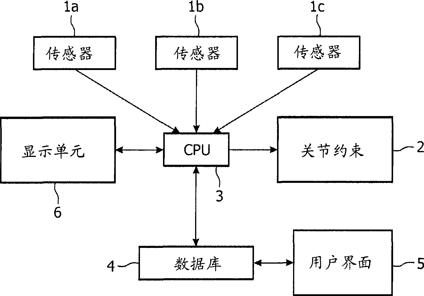
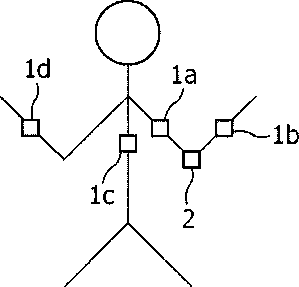
[0019] A single spatial descriptor in a system according to the invention may be any parameter that suitably describes eg the spatial position of a sensor or the orientation of a limb. For example, these individual spatial descriptors can be Cartesian coordinates (x, y, z), Euler angles or quaternions.

[0020] The at least one movement sensor in the system according ...


PUM


Abstract

The present invention relates to a switchable joint constraint system comprising at least one motion sensor, a joint constraint which is switchable between a mobile and an immobile state, a signal processing unit and a database. Motion sensor signals are compared to predefined situations. The joint constraint is switched according to whether predefined situations are met. The present invention furthermore concerns a process for handling sensor signals in such a system. The system may be used to support a constraint induced therapy (CIT) for the treatment of e. g. hemiplegy.

Description

technical field [0001] The invention relates to a joint restraint system. Background technique [0002] Paralysis of one side (hemiplegia) is one of the most common symptoms of neurological disorders. For example, approximately 1.8 million people in Western countries suffer from stroke each year. Their rehabilitation should be aimed at restoring functional use of the affected limb, especially in activities of daily living. The use of an injured limb is a promising approach to achieving rehabilitation success. However, there is a preference not to use the damaged limb. It is common that people simply forget to use the damaged limb. This leads to further aggravation of the condition of the damaged limb. To promote the use of a damaged limb, doctors may place the healthy limb in a plaster cast or restrict it with orthotics. Although this "constraint induced therapy" (constraint inducedtherapy, CIT) is a very harsh method, but can obtain positive results. However, complet...

Claims


Application Information

Patent Timeline
Patent Type & Authority Applications(China)
IPC IPC(8): A61B5/103A61F2/68
CPCA61B5/4528A61B5/1038A61B5/4851
Inventor G·兰弗曼R·D·威尔曼J·特夫鲁格特E·G·J·M·邦杰斯
Owner KONINK PHILIPS ELECTRONICS NV
Why Eureka
Try Eureka