Pneumatic tire

A technology of pneumatic tires and tires, which is applied to tire parts, tire tread/tread pattern, transportation and packaging, etc., and can solve problems such as reduction of ground contact area, uneven wear of ground pressure growth, and residual height of tire shoulder ground , to ease the ground pressure and suppress uneven wear

Inactive Publication Date: 2009-09-02
BRIDGESTONE CORP
View PDF4 Cites 3 Cited by
  • Summary
  • Abstract
  • Description
  • Claims
  • Application Information

AI Technical Summary

Problems solved by technology

[0007] However, in the above-mentioned conventional pneumatic tire, the following situation may occur: the above-mentioned groove portion is crushed by the weight of the vehicle body, so that both ends in the width direction abut against each other, and the ground contact pressure of the shoulder land portion cannot be relieved; or At a relatively early stage when the height of the shoulder land remains sufficiently high, the above-mentioned groove opens on the surface of the shoulder land
In the latter case, not only cannot the ground contact pressure of the shoulder contact area be alleviated, but also the ground contact pressure of the shoulder contact area may further increase due to the reduction of the contact area, which may increase uneven wear
[0008] That is, there is a problem that it is difficult to reliably suppress the occurrence of uneven wear for a long time

Method used


Image

  • Pneumatic tire
  • Pneumatic tire
  • Pneumatic tire

Examples


Embodiment Construction

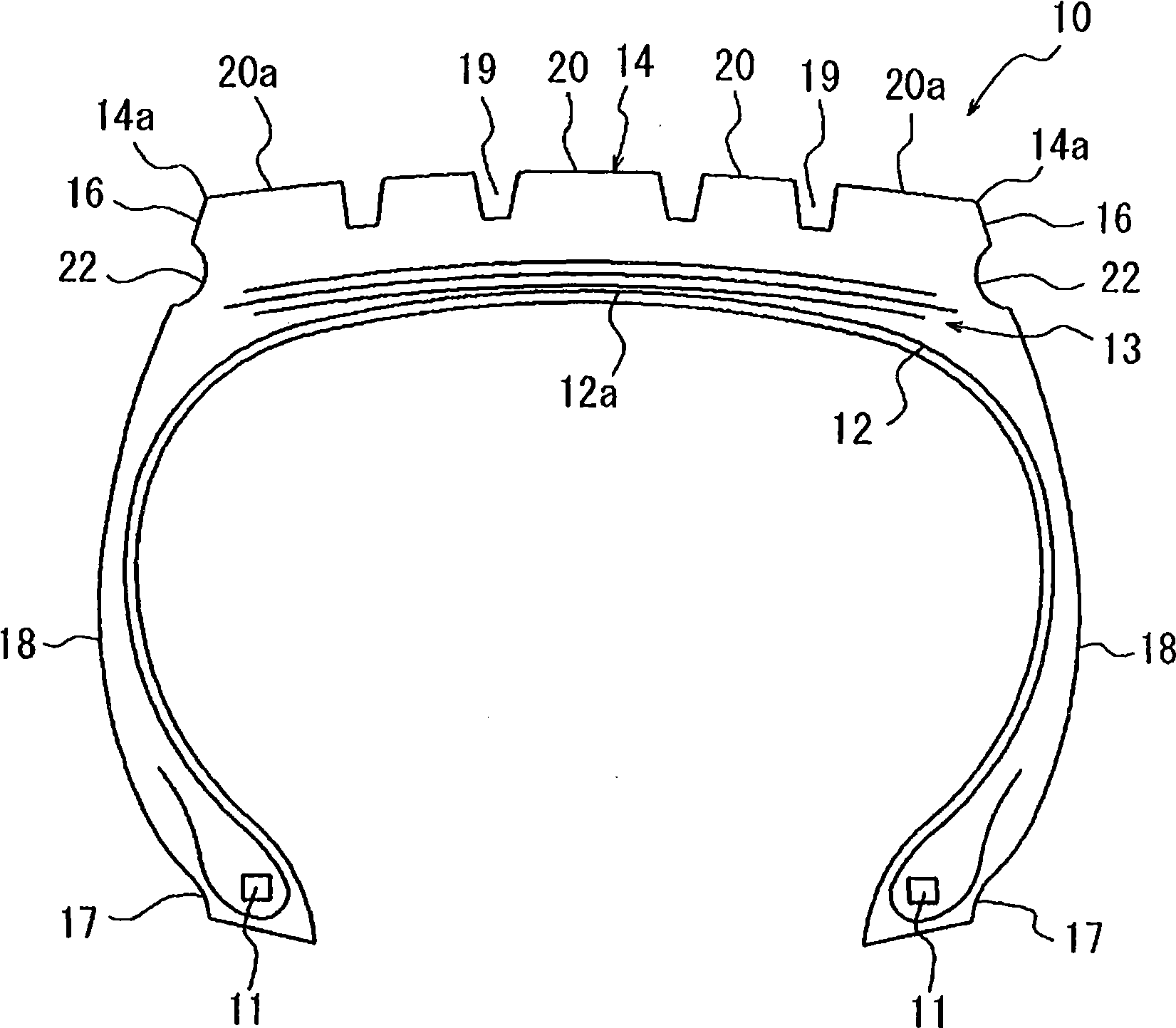
[0046] Below, refer to figure 1 as well as figure 2 One embodiment of the pneumatic tire of the present invention will be described.

[0047] figure 1 It is a cross-sectional view showing a pneumatic tire 10 along the tire width direction, and a belt layer 13 and a belt layer 13 are provided in this order on the outer side in the tire radial direction of the crown portion 12a of the carcass layer 12 extending annularly between a pair of left and right beads 11. The tread contact surface 14. In addition, in the illustrated example, the belt layer 13 has multiple layers.

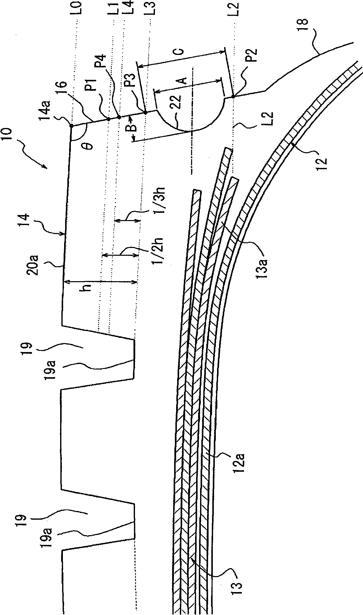
[0048] In addition, in the present embodiment, the pneumatic tire 10 includes a shoulder reinforcement portion 16, a bead portion 17, and a sidewall portion 18; the shoulder reinforcement portion 16 is directed radially inward from both ends 14a in the width direction of the tread contact surface 14, respectively. Extension; the bead portion 17 is formed by embedding the bead 11 inside; the sidewall porti...


PUM


Abstract

The invention provides a pneumatic tire capable of surely restraining uneven wear for a long term. A groove portion 22 recessed in the tire width direction is formed along the tire circumferential direction on a buttress portion 16 extending inwardly in the tire radial direction from the widthwise end portion 14a of the tread portion 14, the groove portion 22 being situated between a first intersecting portion P1 where a first virtual line L1 connecting locations of half depths of plurality of main grooves 19 in the tire width direction intersects with a surface of the buttress portion 16, and a second intersecting portion P2 where a second virtual line L2 extending outwardly in the tire width direction from each of both ends of an innermost belt 13a in the tire width direction disposed in an innermost side of the belt layer 13 in the tire radial direction intersects with the surface of the buttress portion 16, and an opening width A of the groove portion 22 in the buttress portion 16 is larger than a depth B of the groove portion 22.

Description

technical field [0001] The present invention relates to a pneumatic tire capable of suppressing uneven wear. Background technique [0002] As such a pneumatic tire, structures such as those shown in the following Patent Documents 1 to 4 are known: shoulder reinforcements (buttresses) extending inward in the tire radial direction from both ends in the width direction of the tread contact surface are respectively formed with buttresses. A groove extending in the tire circumferential direction. In addition, when the pneumatic tire is mounted on a vehicle and the tread contact surface is in contact with the ground, the width of the groove portion is deformed to be narrowed by the weight of the vehicle, thereby suppressing the shoulders located at both ends in the width direction of the tread contact surface. The ground contact pressure of the land portion is locally increased, thereby suppressing uneven wear such as detachment of the shoulder land portion. [0003] Patent Docu...

Claims


Application Information

Patent Timeline
Patent Type & Authority Applications(China)
IPC IPC(8): B60C11/01
CPCB60C11/01
Inventor 阿部康典
Owner BRIDGESTONE CORP
Why Eureka
Try Eureka