Dial switch

A dial-type, switch technology, applied in the direction of electric switches, electrical components, circuits, etc., can solve the problem of not being able to obtain the feeling of clicking sound, achieve the effect of smooth reciprocating motion and miniaturization

Inactive Publication Date: 2012-07-04
SUMITOMO WIRING SYST LTD
View PDF4 Cites 5 Cited by
  • Summary
  • Abstract
  • Description
  • Claims
  • Application Information

AI Technical Summary

Problems solved by technology

[0009] However, also in this dial switch, a consistent click feeling cannot be obtained in the rotational operation of the dial knob 102.

Method used


Image

  • Dial switch
  • Dial switch
  • Dial switch

Examples


Embodiment Construction

[0036] Hereinafter, an embodiment of the present invention will be described with reference to the accompanying drawings.

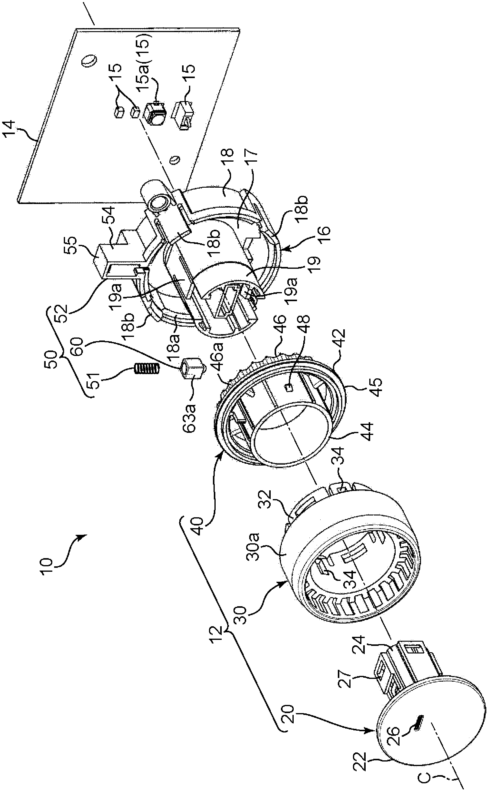
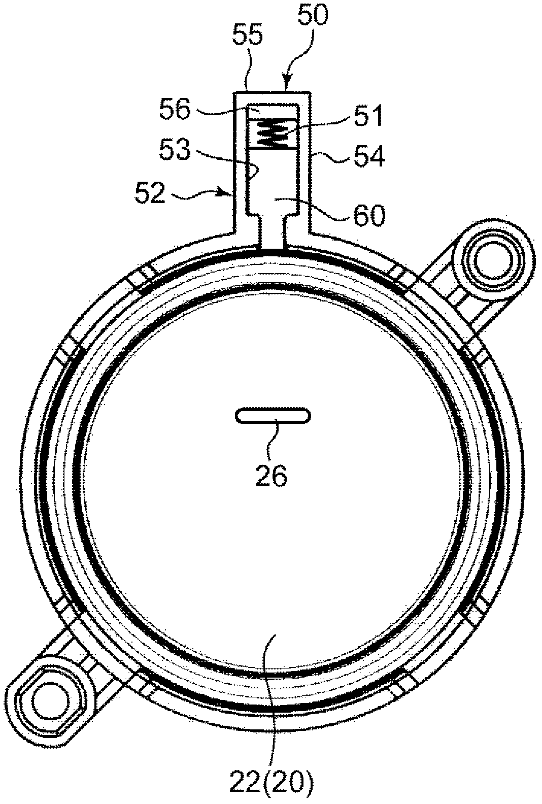
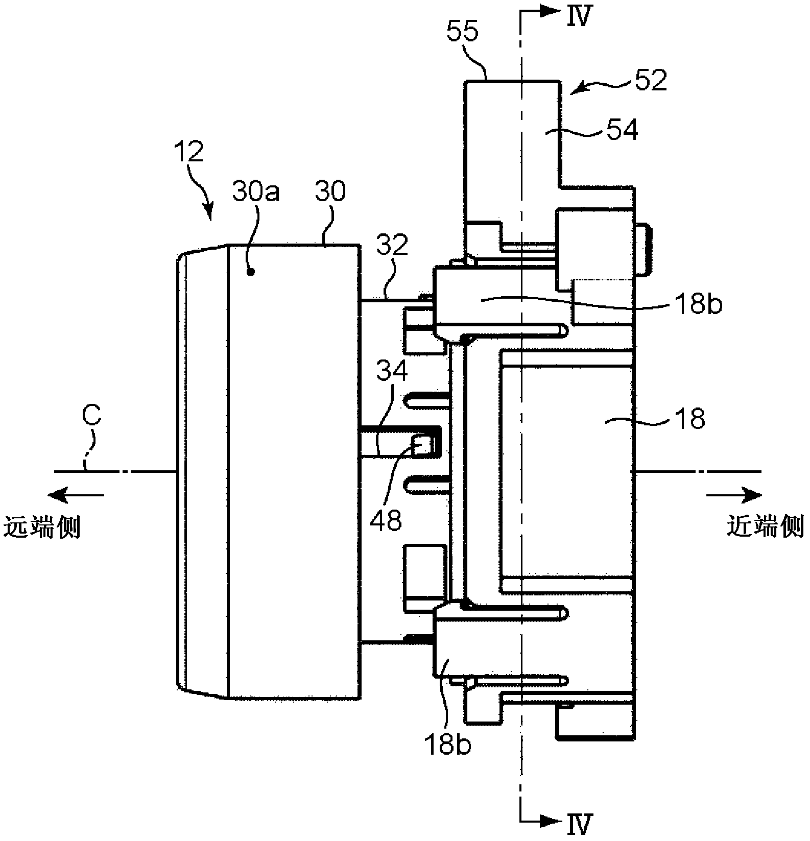
[0037] The dial switch according to this embodiment is a type of dial switch used to operate electronic equipment and the like, and is provided, for example, on an operation panel constituting the interior of a vehicle or the like. Such as Figure 1 to Figure 5 As shown, the dial switch includes a rotatably operable dial knob 12 and a support member 16 by which the dial knob 12 is rotatably supported on a printed circuit board 14 . On the surface of the printed circuit board 14 where the supporting member 16 is provided, circuits are arranged and a plurality of electronic components 15, 15... are mounted.

[0038] The dial knob 12 is a part that rotates around a central axis C, and includes a cylindrical dial member 30 , a switch member 20 fitted in the interior of a distal end portion of the dial member 30 , and a rotary knob that rotates together with ...


PUM


Abstract

A dial switch is provided with: a pivoting section (40) having an uneven peripheral surface (46a); a plunger (60); a holding section (52) for holding the plunger (60) so that the plunger (60) can reciprocate; and a coiled spring (51) for pressing the plunger (60). The holding section (52) has a guide surface (53) extending in the direction in which the plunger (60) moves and surrounding the plunger (60) from the outside. The plunger (60) is provided with: an outer wall section (63) which has an outer peripheral surface (63a) located close to the guide surface (53), and also has an inner peripheral surface (63b) having an inner diameter greater than the outer diameter of the coiled spring (51); and an inner shaft (64) which is located inside the outer wall section (63) and has a rear end located further toward the front side than the rear end of the outer wall section (63), the inner shaft (64) being adapted to enable the coil spring (51) to be mounted on the outer side thereof. The difference between the outer diameter of the inner shaft (64) and the inner diameter of the coiled spring (51) is less than the difference between the inner diameter of the outer wall section (63) and the outer diameter of the coiled spring (51).

Description

technical field [0001] The present invention relates to a dial switch for operating electronic equipment or the like mounted on a vehicle or the like. Background technique [0002] Conventionally, a switch disclosed in Patent Document 1 as a dial switch is known, which gives a user a feeling of a click sound when the user rotates a dial knob to operate an electronic device or the like. [0003] Such as Figure 8 and Figure 9 As shown, the dial switch includes an annular dial knob 102 and a support member (not shown in the drawings) that rotatably supports the dial knob 102 . The support member is provided with a detent portion 104 that gives the user a click sensation when the user rotates the dial knob 102 . [0004] The dial knob 102 has an uneven peripheral surface 106 on which radially indented recesses and radially protruding protrusions repeat alternately in the circumferential direction. The latch portion 104 includes a plunger 108 formed of a metal ball, a plunge...

Claims


Application Information

Patent Timeline
Patent Type & Authority Applications(China)
IPC IPC(8): H01H19/11H01H19/63H01H25/00H01H89/00
CPCH01H19/63H01H19/11
Inventor 中岛浩胜茶园悟
Owner SUMITOMO WIRING SYST LTD
Why Eureka
Try Eureka