Linear actuator, electric brush, electric cutting machine and electric air pump

a linear actuator and electric brush technology, applied in the field of linear actuators, can solve the problems of power loss, efficiency sacrifice, and inability to easily downsize, and achieve the effects of improving assembly efficiency, simple configuration, and stable linear reciprocation

Active Publication Date: 2018-07-24
MITSUMI ELECTRIC CO LTD
View PDF18 Cites 2 Cited by
  • Summary
  • Abstract
  • Description
  • Claims
  • Application Information

AI Technical Summary

Benefits of technology

[0015]According to the present invention, an electromagnet coil and a magnet whose magnetization direction is set to the coil-winding axis are disposed to face each other in the coil-winding axis direction, and a movable member is supported in a fixing body by an elastic body fixed at its both end portions in the coil-winding axis direction such that the movable member can reciprocate in the coil-winding axis direction. With this configuration, downsizing can be achieved with a simple configuration, and stable linear reciprocation can be provided while achieving improvement in assemblability and cost reduction.

Problems solved by technology

Such a structure in which a motion direction conversion mechanism is used requires the space for the complicated mechanism for converting the driving direction, and therefore cannot be easily downsized.
In addition, the motion conversion mechanism generates significant noise at the time of driving, and causes power loss, and therefore the efficiency may be sacrificed.

Method used


Image

  • Linear actuator, electric brush, electric cutting machine and electric air pump
  • Linear actuator, electric brush, electric cutting machine and electric air pump
  • Linear actuator, electric brush, electric cutting machine and electric air pump

Examples


embodiment 1

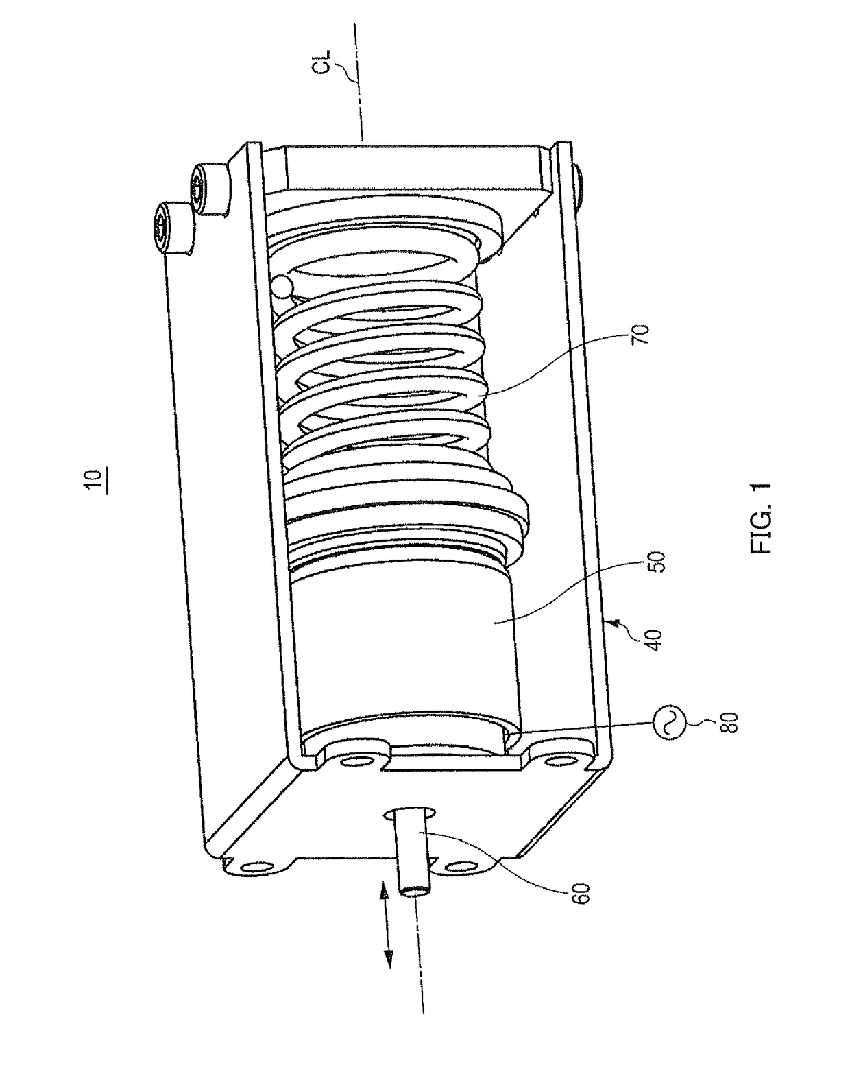
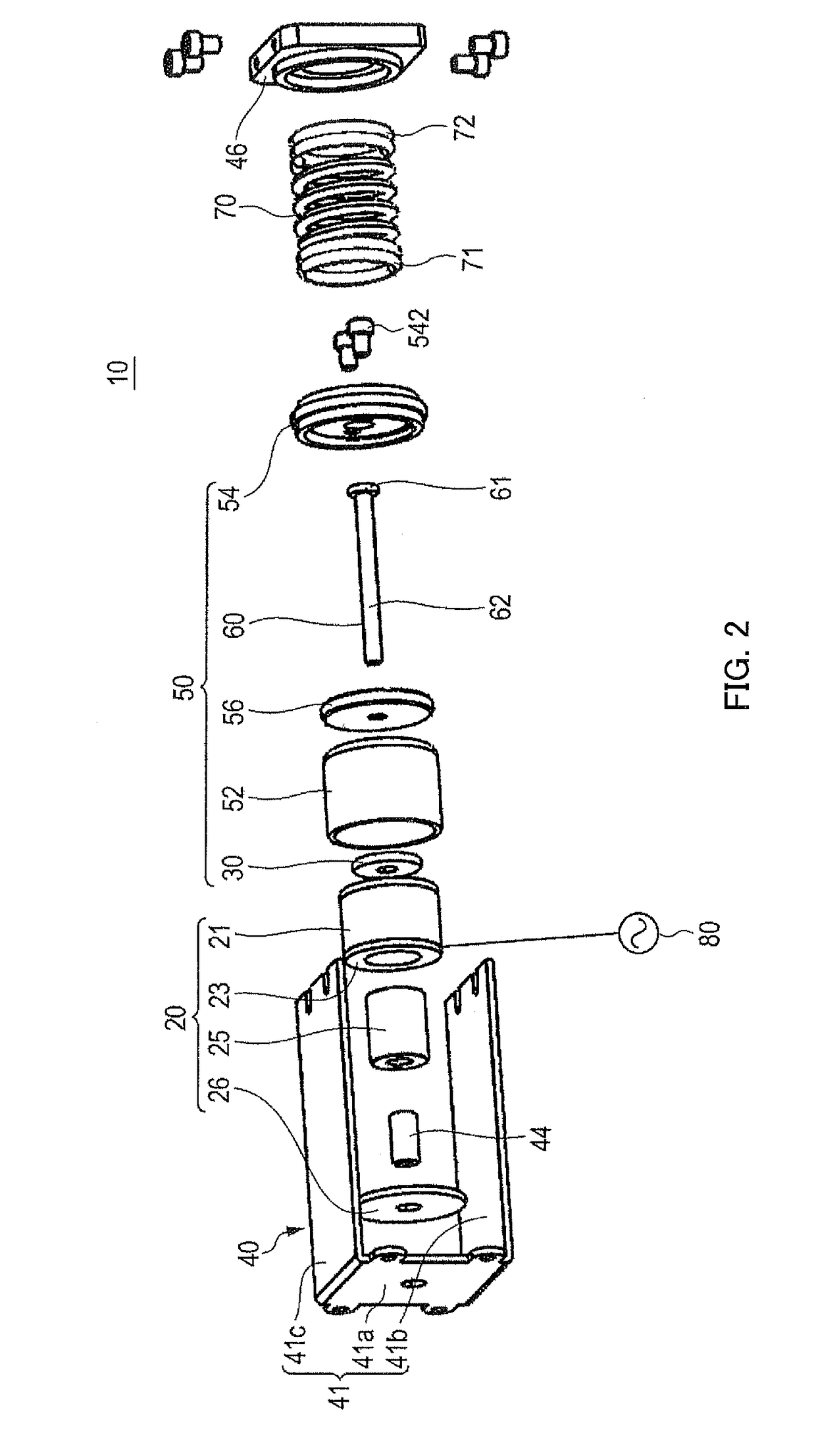
[0041]FIG. 1 illustrates an external appearance of a linear actuator according to Embodiment 1 of the present invention, and FIG. 2 is an exploded perspective view of the linear actuator.

[0042]Linear actuator 10 illustrated in FIG. 1 and FIG. 2 includes fixing body 40, movable member 50 including output shaft 60, and elastic body 70 that supports movable member 50 in fixing body 40 such that movable member 50 is movable along an axis (CL) direction of output shaft 60.

[0043]In linear actuator 10 illustrated in FIG. 1 and FIG. 2, movable member 50 reciprocates along the axis CL direction with respect to fixing body 40 with power supplied from alternating-current supplying section 80, and output shaft 60 reciprocates along the axis CL direction (indicated by arrow in FIG. 1) along with the reciprocation of movable member 50, whereby the reciprocation is output to the outside.

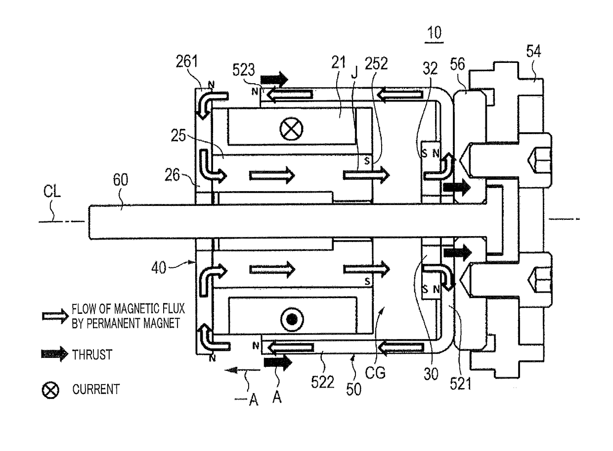
[0044]FIG. 3 is a schematic sectional view illustrating a configuration of a main part of the linear actuator.

[0...

embodiment 2

[0093]FIG. 6 is a planer sectional view illustrating a magnetic circuit of linear actuator 10A according to Embodiment 2 of the present invention.

[0094]Linear actuator 10A illustrated in FIG. 6 has a basic configuration similar to that of linear actuator 10 of Embodiment 1 illustrated in FIGS. 1 to 4. Linear actuator 10A differs from linear actuator 10 in the shape of the yoke (yoke 52 in linear actuator 10) on movable member 50 side that is a part of a magnetic circuit and in the shape of the core (plate core 26 in linear actuator 10) on fixing body 40 side. Since functions and shapes of other configurations are similar to those of linear actuator 10, the same components are denoted by the same reference numerals, and the description thereof will be omitted.

[0095]Linear actuator 10A illustrated in FIG. 6 includes fixing body 40A including electromagnet 20A and an actuator frame not illustrated (baseplate 41 and spring receiving part 46 illustrated in FIG. 2 and FIG. 3), and movable...

embodiment 3

[0100]FIG. 7 is a planer sectional view illustrating a magnetic circuit of linear actuator 10B according to Embodiment 3 of the present invention.

[0101]Linear actuator 10B has a basic configuration similar to that of linear actuator 10 of Embodiment 1 illustrated in FIGS. 1 to 4. Linear actuator 10B differs from linear actuator 10 in the shape of the yoke on movable member 50 side that is a part of magnetic circuit (yoke 52 of actuator 10), and the shape of the core on fixing body 40 side (plate core 26 of actuator 10). Since functions and shapes of other configurations are similar to those of linear actuator 10, the same components are denoted by the same reference numerals, and the description thereof will be omitted.

[0102]Linear actuator 10B illustrated in FIG. 6 includes fixing body 40B including electromagnet 20B and an actuator frame not illustrated (baseplate 41 and spring receiving part 46 illustrated in FIG. 2 and FIG. 3), and movable member 50B having output shaft 60. Mova...


PUM


Abstract

A linear actuator that can achieve downsizing with a simple configuration, and can provide stable linear reciprocation while achieving improvement in assemblability and cost reduction. In the actuator, movable member 50 faces coil 21 in the winding axis CL direction of coil 21, and in addition, includes magnet 30 magnetized in the coil-winding axis CL direction in a unipolar fashion and output shaft 60 extending in the CL direction. Elastic body 70 is disposed along the coil-winding axis CL direction and configured to deform in that direction to supports movable member 50 such that movable member 50 can reciprocate along the coil-winding axis CL direction. Elastic body 70 is fixed to fixing body 40 and movable member 50 at both ends 71 and 72 in the coil-winding axis CL direction such that central air gap CG is formed between electromagnet 20 and magnet 30.

Description

CROSS REFERENCE TO RELATED APPLICATIONS[0001]This application is entitled to and claims the benefit of Japanese Patent Application No. 2014-201783, filed on Sep. 30, 2014, the disclosure of which including the specification, drawings and abstract is incorporated herein by reference in its entirety.TECHNICAL FIELD[0002]The present invention relates to a linear actuator that provides linear power, an electric brush, an electric cutting machine and an electric air pump.BACKGROUND ART[0003]Conventionally, in electric brushes used in facial equipment, electric toothbrushes, electric razors, electric shoeshine machines, electric car-washing machines and the like, a movable part such as a brush head of facial equipment, a brush part of a toothbrush, a blade, a shoe polishing brush, and a car-washing brush reciprocates for aesthetic cares of skin, teeth, shaving and the like, and for polishing and washing of shoes and a car body. In addition, conventionally, in electric cutting machines suc...

Claims


Application Information

Patent Timeline
Patent Type & Authority Patents(United States)
IPC IPC(8): H02K33/16A61C17/34
CPCA61C17/3445H02K33/16
Inventor OKAWA, TATSUNORITAKAHASHI, YUKISEKIGUCHI, CHIKARAINAMOTO, SHIGENORI
Owner MITSUMI ELECTRIC CO LTD
Why Eureka
Try Eureka