

Pneumatic tire
A technology for pneumatic tires and tires, applied in tire parts, tire treads/tread patterns, transportation and packaging, etc., can solve the problem of not being able to suppress uneven tread wear, etc. The effect of uneven wear and avoiding the deterioration of rigidity balance
- Summary
- Abstract
- Description
- Claims
- Application Information
AI Technical Summary
Problems solved by technology
Method used
Image

Examples
Embodiment approach
[0038] (1) In the above-mentioned embodiment, the example in which the dimple rows are provided on the edge portions 30, 40 on both sides of the tire width direction of the main grooves 4, 6 is shown, but the present invention is not limited thereto, Appropriate changes are made to the uneven wear pattern that occurs. For example, if the wear speed is particularly slow at the edge portion 30 inside the width direction of the main grooves 4, 6, then it can be as follows: Figure 4 As shown, only the row of dimples is provided on the edge portion 30. On the contrary, if the wear speed is particularly slow at the edge portion 40 on the outer side of the main groove 4, 6 in the tire width direction, it can be as follows: Figure 5 As shown, the dimple rows are provided only on the edge portion 40 .
[0039] (2) In the above-mentioned embodiment, the example in which the first edge portion extends in the tire circumferential direction was shown, but the present invention is not li...
Embodiment
[0045] Examples and the like which specifically show the configuration and effects of the present invention will be described below. In addition, various performance evaluations of the tires were performed as follows.
[0046] (1) Uneven wear resistance (uneven wear ratio)
[0047] The test tire (tire specification: LT265 / 75R16) was mounted on a diesel truck (6600cc, 4WD) as the rear tire, and the rear tire pressure was set at 520kPa. After driving 20,000 km on ordinary roads, the uneven wear ratio (center side main groove wear amount / shoulder side main groove wear amount). The closer the uneven wear ratio is to 1, the closer the wear is to uniform wear, that is, it means that the uneven wear resistance is excellent.
[0048] (20) Drainage performance
[0049] Experimental tires (tire specifications: LT265 / 75R16) were mounted on a diesel truck (6600cc, 4WD) as rear tires, the rear tire pressure was 520kPa, the front tire pressure was 420kPa, and the truck was placed on a we...
Embodiment 1、2
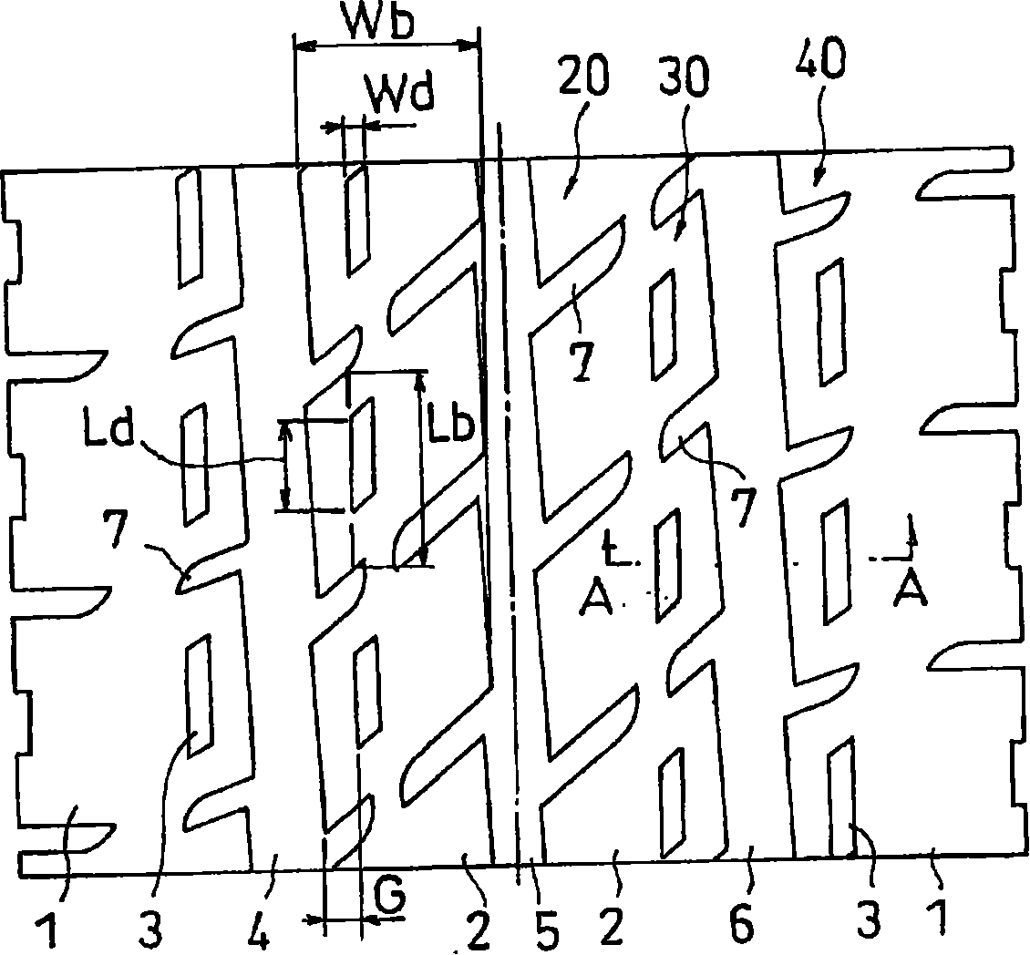
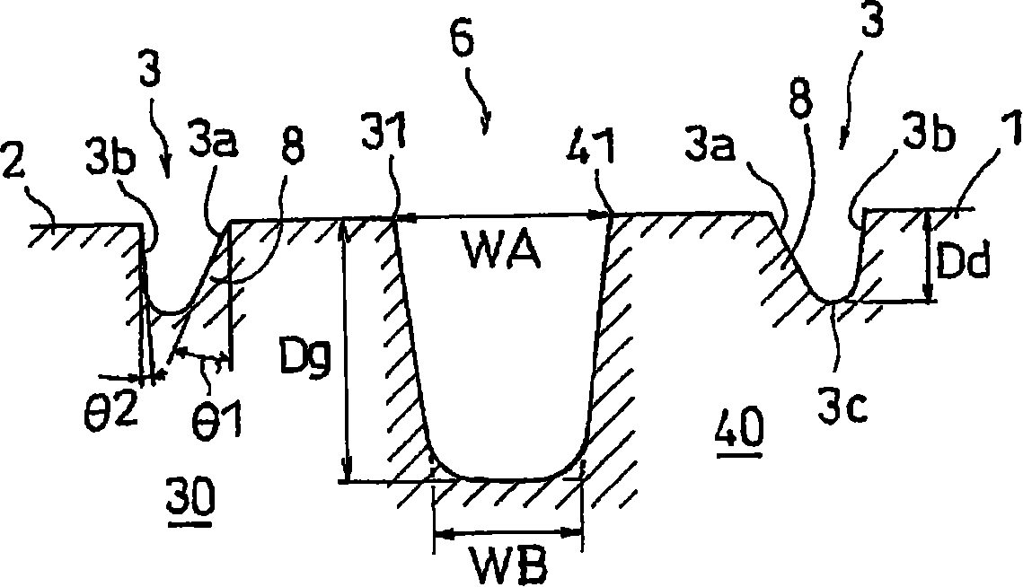
[0053] exist figure 1 On the tread shown, the pneumatic tire in which the main groove on the center side has a U-shaped cross-section and the groove wall angles θ1 and θ2 of the pits are both 0° is Example 1, and the groove wall angle θ1 is set to 10° in the same manner. On the other hand, the pneumatic tire provided with the reinforcing part on the dimple is the embodiment 2. In addition, the depth Dg of the main groove is 12.5 mm, the ratio Dd / Dg of the depth of the dimple to the depth of the main groove is 0.40, the ratio Wd / Wb of the width of the dimple to the width of the block is 0.11, and the distance between the dimple and the edge end is 0.11. The distance G in the tire width direction was 9 mm, and the ratio Ld / Lb of the dimple length to the block length was 0.50. The results are shown in Table 1.
[0054] Table 1
[0055] The shape of the main groove 5
[0056] As can be seen from Table 1, in Comparative Example 1, the uneven wear ratio was the larges...
PUM
 Abstract
Description
Claims
Application Information