Purification system having pipelines arranged at different levels in height direction

Active Publication Date: 2020-07-02
LAIR LIQUIDE SA POUR LETUDE & LEXPLOITATION DES PROCEDES GEORGES CLAUDE
View PDF0 Cites 0 Cited by
  • Summary
  • Abstract
  • Description
  • Claims
  • Application Information

AI Technical Summary

Benefits of technology

The patent text describes a method to reduce the space taken up by a purification system on a construction site. The technical effects of the invention include reducing the width and length of the system, as well as minimizing the space at the edges of the system. The method also allows for easier servicing and maintenance of the system, as well as reducing the requirement for additional overhaul space.

Problems solved by technology

Purification system piping is arranged differently from normal-temperature pipelines and low-temperature pipelines in an air separation apparatus; the pipeline working temperature is high, operating conditions are numerous, changeover operations are complex, air separation site limits are generally restrictive, and different pipeline arrangement schemes result in large differences in apparatus long-term running energy consumption.
1) The horizontal arrangement of three large pipelines in parallel requires a very large amount of site space.
2) In order to avoid collision, two large pipelines connected to purification (the first inlet pipeline 101 and the first outlet pipeline 102, or the second inlet pipeline 201 and the second outlet pipeline 202) cannot be arranged in an overlapping manner, and the first outlet pipeline 102 and second outlet pipeline 202 are arranged in a splayed manner, with the result that a larger area of ground is taken up.
3) An electric heater 70 is disposed outside a zone module, and branch pipes 60 are connected to the first inlet pipeline 101 and second inlet pipeline 201, further increasing the area of ground taken up.
4) The three-stem valves are hoisted from above, therefore it is not only necessary to ensure that the space above the three-stem valves is not occupied. When a mobile crane is used to hoist the three-stem valves, it is necessary to ensure that there is sufficient space at the block periphery to park the mobile crane.

Method used


Image

  • Purification system having pipelines arranged at different levels in height direction
  • Purification system having pipelines arranged at different levels in height direction
  • Purification system having pipelines arranged at different levels in height direction

Examples


embodiment 1

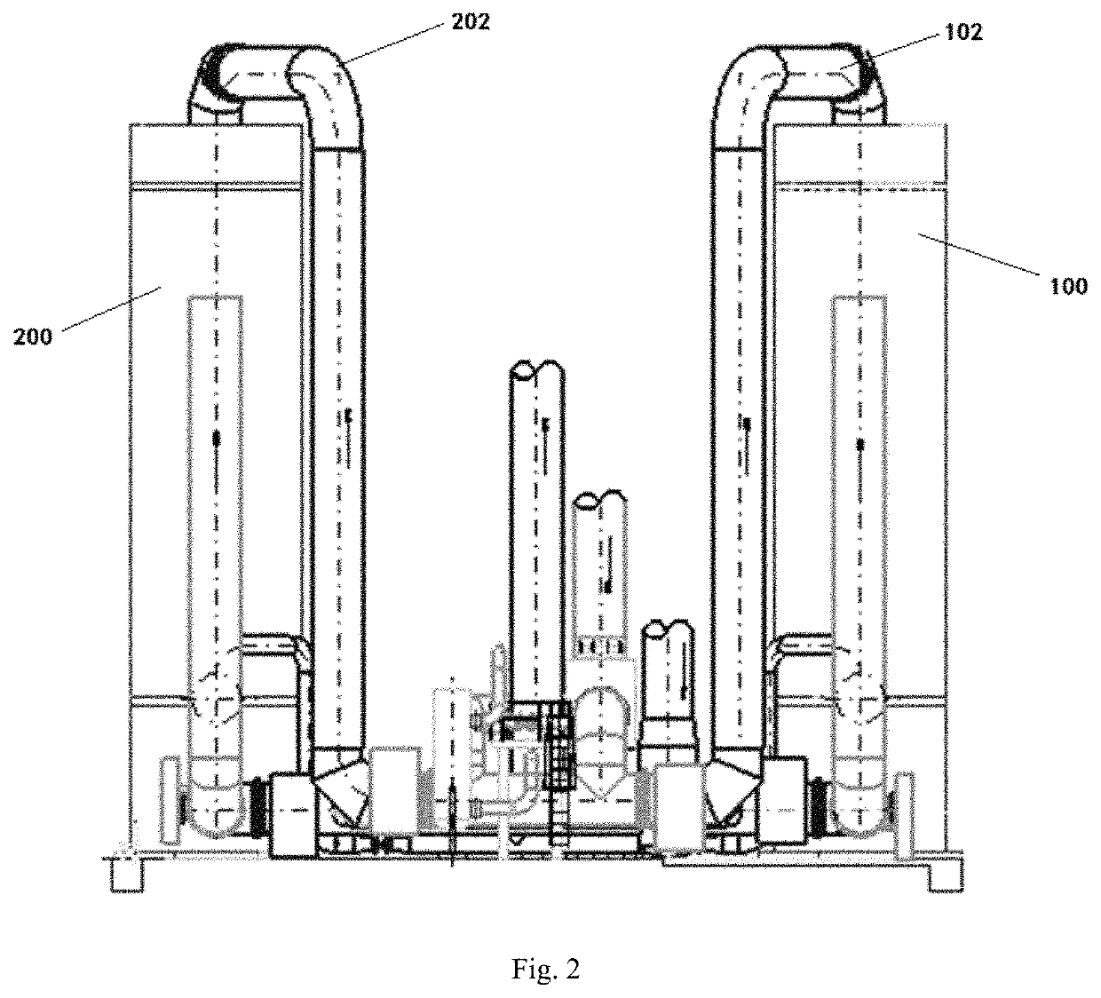
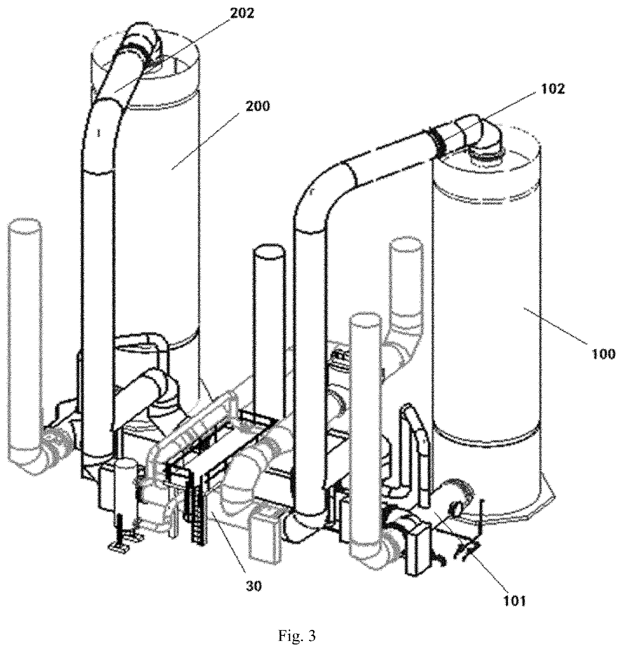
[0065]The air input pipeline 10, the air output pipeline 20 and the waste nitrogen input pipeline 30 are disposed at different heights respectively between the first purifier 100 and the second purifier 200, in such a way as to be disposed in parallel in a vertical space. The air input pipeline 10 is disposed at the bottom, the waste nitrogen input pipeline 30 is disposed in the middle, and the air output pipeline 20 is disposed at the top; gaps between the three pipelines are appropriate for facilitating the overhaul of the three-stem valves. The total area of ground projections of the air input pipeline 10, the air output pipeline 20 and the waste nitrogen input pipeline 30 arranged in this embodiment is no smaller than a projection area of a single air input pipeline; moreover, the furthest distance between ground projections of the three pipelines arranged in this embodiment (the value W of the pipeline arrangement in this embodiment) is smaller than the furthest distance betwee...

embodiment 2

[0069]The air input pipeline 10, the air output pipeline 20 and the waste nitrogen input pipeline 30 are disposed at different heights respectively between the first purifier 100 and the second purifier 200, in such a way as to be disposed in parallel in a vertical space. The air input pipeline 10 is disposed at the bottom, and the waste nitrogen input pipeline 30 and air output pipeline 20 are disposed side by side at the top; gaps between the three pipelines are appropriate for facilitating the overhaul of the three-stem valves. The total area of ground projections of the three pipelines arranged in this embodiment is greater than a projection area of a single air input pipeline; moreover, the furthest distance between ground projections of the three pipelines arranged in this embodiment (the value W of the pipeline arrangement in this embodiment) is smaller than the furthest distance between the three pipelines when they are disposed in parallel side by side on the ground (the va...

embodiment 3

[0072]The air input pipeline 10, the air output pipeline 20 and the waste nitrogen input pipeline 30 are disposed at different heights respectively between the first purifier 100 and the second purifier 200, in such a way as to be disposed in parallel in a vertical space. The air input pipeline 10 and the waste nitrogen input pipeline 30 are disposed side by side in parallel at the bottom, and the air output pipeline 30 is disposed in a space above; gaps between the three pipelines are appropriate for facilitating the overhaul of the three-stem valves. The total area of ground projections of the air input pipeline 10, the air output pipeline 20 and the waste nitrogen input pipeline 30 arranged in this embodiment is greater than a projection area of a single air input pipeline 10; moreover, the furthest distance between ground projections of the three pipelines arranged in this embodiment (the value W of the pipeline arrangement in this embodiment) is smaller than the furthest distan...


PUM


Abstract

Disclosed in the present invention is a purification system having pipelines arranged at different levels in a height direction, comprising: a first purifier and a second purifier disposed side by side symmetrically; an air input pipeline, an air output pipeline and a waste nitrogen input pipeline, wherein the air input pipeline, the air output pipeline and the waste nitrogen input pipeline are disposed at different heights, the gap between pairs of pipelines being determined so as to facilitate overhaul of three-stem valves, a value W being smaller than a value W when the air input pipeline, the air output pipeline and the waste nitrogen input pipeline are arranged in parallel on the ground, and the purification system further comprises: a three-stem valve platform formed by a framework structure in a number of levels, to facilitate overhaul of the three-stem valves. In the present invention, the rational layout of purification system pipelines greatly reduces the ground space taken up by the purification system, and the provision of the three-stem valve platform enables a hoisting device and a forklift truck to be conveniently used instead of a mobile crane, reducing the requirement for additional overhaul space.

Description

CROSS REFERENCE TO RELATED APPLICATIONS[0001]This application claims the benefit of priority under 35 U.S.C. § 119 (a) and (b) to Chinese patent application No. CN201811612933.0, filed Dec. 27, 2018, the entire contents of which are incorporated herein by reference.FIELD OF THE INVENTION[0002]The present invention relates, in the field of air separation, to a layout of a purification system located in an air separation zone, and in particular relates to a purification system having pipelines arranged at different levels in a height direction. The main purpose is to improve the modular arrangement of the purification system of the air separation zone, in order to save a greater amount of site space.BACKGROUND OF THE INVENTION[0003]As industries such as the petroleum chemical industry, metallurgy and pharmaceuticals have developed at a rapid pace, air separation technology has also developed rapidly, with air separation apparatuses as a whole developing towards large-scale, low-cost r...

Claims


Application Information

Patent Timeline
IPC IPC(8): B01D53/04
CPCB01D2257/102B01D53/0446B01D53/0438B01D2256/12B01D2259/402F25J3/0489F25J3/04169B01D53/0423B01D53/02B01D53/0407B01D53/26
Inventor XIANG, WENJUANLI, ZHIQIANGSHI, YUNQINGWANG, WENHUA
Owner LAIR LIQUIDE SA POUR LETUDE & LEXPLOITATION DES PROCEDES GEORGES CLAUDE
Why Eureka
Try Eureka