Underground cable and wire laying robot

A technology for underground cables and robots, which is applied to cable laying equipment, manipulators, motor vehicles, etc., and can solve problems such as incorrect calculation of the actual height of sand, gravel and soil, and occlusion

Inactive Publication Date: 2020-10-20
GUANGZHOU LIANJIANG SOFTWARE DEV LLC
View PDF10 Cites 0 Cited by
  • Summary
  • Abstract
  • Description
  • Claims
  • Application Information

AI Technical Summary

Problems solved by technology

[0003] Based on the inventor's discovery above, the existing methods mainly have the following deficiencies, such as: because the infrared sensor on the equipment is installed on the base plate, and the caterpillars provided on the base plate are triangular, and the lower end surface is triangular cone-shaped. During the movement, all the weight of the equip

Method used


Image

  • Underground cable and wire laying robot
  • Underground cable and wire laying robot
  • Underground cable and wire laying robot

Examples


Embodiment 1

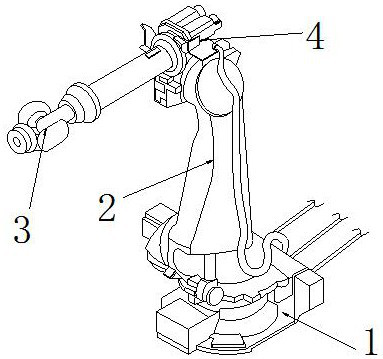
[0027] as attached figure 1 to attach Figure 4 Shown:

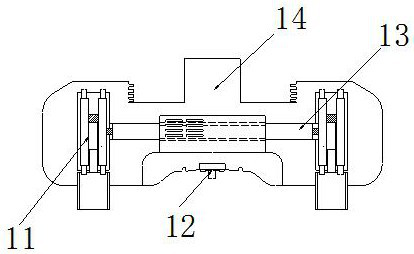
[0028] The present invention provides an underground cable and wire laying robot, the structure of which includes a mobile device 1, a support column 2, a camera 3, and a central control 4. The mobile device 1 is embedded and installed directly under the support column 2, and the support column 2 The central control 4 is installed on the upper surface by welding, and the camera 3 is inlaid and mounted on the left end surface of the central control 4; the mobile device 1 includes a support device 11, an infrared scanner 12, a power rod 13, and a support shaft 14. The support device 11 is symmetrically installed on the left and right sides of the power rod 13, the infrared scanner 12 is embedded and installed directly below the support shaft 14, and the outer side of the power rod 13 is embedded with the infrared scanner 12. The support shaft 14 is threadedly connected to the lower end surface of the support column 2, an...

Embodiment 2

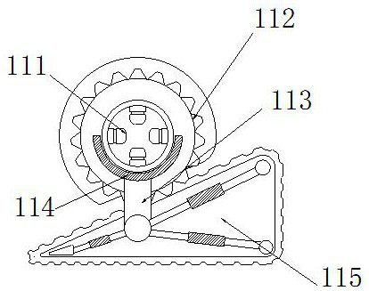
[0034] as attached Figure 4 to attach Figure 8 Shown:

[0035]Wherein, the pressure dividing mechanism 115 includes a crawler belt 5a, a movable rod 5b, a connecting shaft 5c, a tension plate 5d, and a second connecting shaft 5e. Embedded and installed on the left and right sides of the connecting shaft 5c, the upper end surface of the tension plate 5d is embedded with the second connecting shaft 5e, and the upper end surface of the second connecting shaft 5e is connected to the connecting rod 113 by welding. There are six shafts 5c, and the distribution angle is consistent with the outline of the outer end of the pressure dividing mechanism 115. Using the segmented design, when the upper end is under pressure, the connecting shaft 5c can shrink and reduce pressure, effectively reducing the concentration of pressure.

[0036] The connecting shaft 5c includes a threaded connection end 5c1, a spring 5c2, an interaction mechanism 5c3, and a fixed block 5c4. The thread connect...


PUM


Abstract

The invention discloses an underground cable and wire laying robot. The robot structurally comprises a mobile device, a supporting column, a camera and a central controller. The mobile equipment is embedded and fixedly mounted under the supporting column. A central controller is mounted on the upper end surface of the supporting column through welding. The camera is embedded and clamped on the left side end surface of the central controller. When the pressure at the upper end of the equipment in movement is unbalanced or the pressure is locally concentrated due to the pressure, the triangularouter contour formed by the movable rod and the crawler belt in the pressure dividing mechanism can be used for uniformly transmitting the soil to the lower end plane and the tension plate, so that the problem of calculation errors of the infrared scanner due to soil accumulation or forming of a concave outer contour caused by uneven pressure dividing of the outer contour due to gravity stress canbe effectively avoided.

Description

technical field [0001] The invention belongs to the field of cables and wires, and more specifically relates to a robot for laying underground cables and wires. Background technique [0002] The wire and cable laying robot is a kind of robot that calculates the surrounding environment and route through the central control system, and then reversely rotates the wire winder to lay the cables wound on its surface on the ground. Infrared sensors are respectively installed on the mechanical arm and the chassis of the equipment. [0003] Based on the inventor's discovery above, the existing methods mainly have the following deficiencies, such as: because the infrared sensor on the equipment is installed on the base plate, and the caterpillars provided on the base plate are triangular, and the lower end surface is triangular cone-shaped. During the movement, all the weight of the equipment will be transferred to the lower end surface of the conical track profile on the left and ri...

Claims


Application Information

Patent Timeline
IPC IPC(8): H02G1/06B25J5/00B25J11/00B62D55/084
CPCB25J5/005B25J11/00B62D55/084H02G1/06
Inventor 朱寒梅
Owner GUANGZHOU LIANJIANG SOFTWARE DEV LLC
Why Eureka
Try Eureka