Pill dispensing method and apparatus

a technology for dispensing methods and pills, applied in the direction of apparatus for dispensing discrete articles, instruments, de-stacking articles, etc., can solve the problems of slowing down the feed of pills and limited speed at which remaining pills can be returned to storage containers

Active Publication Date: 2014-08-05
CZARNEK & ORKIN LAB
View PDF10 Cites 6 Cited by
  • Summary
  • Abstract
  • Description
  • Claims
  • Application Information

AI Technical Summary

Benefits of technology

[0004]A pill dispensing machine includes a hopper or chute into which pills to be counted are poured from a bulk container. A cassette inside the machine includes a plurality of rotors that move the pills along a spiral path. A gate incorporated into the path of pills exiting the cassette facilitates directing the pills either toward a pill bottle or a storage container.
[0006]The use of multiple rotors allows controlled rate of feeding and separation of pills reaching a counter into a single line or queue, thereby preventing miscounts. To separate the pills into a single line or queue, the rotors move at different speeds, with the outer rotor(s) rotating faster than inner rotor(s) thereby facilitating the separation. Radial groves, indentations, or protrusions can be provided in one or more of the rotors to avoid pills from rolling and thereby enabling fast and well controlled movement of pills.
[0007]Once the desired number of pills is dispensed into a pill bottle, any remaining pills in the cassette can be returned to the storage container by increasing the speed of the inner rotor(s). Having the outer rotor(s) rotating faster than the inner rotor(s) facilitates separating pills in a single line or queue. However, this approach slows down the feed of the pills when one wants to return remaining pills to the storage container. If the rotors are powered by a single motor through a set of fixed gears, then the speed at which remaining pills can be returned to the storage container is limited by the maximum allowable speed of the outer rotor. However, if the rotors are rotated separately by dedicated motors the speeds of the rotors can be adjusted as needed. During counting of the pills, the speeds of the rotors can be different for different rotors. During the returning of the remaining pills, the speed(s) of the inner rotor(s) can be brought up to the speed of the outermost rotor, maximizing the overall throughput of the machine.
[0008]In a flat or planar rotor configuration, pills move along a smooth spiral path. However, a conical or convex rotor configuration desirably defines a stepped spiral path. This latter geometry facilitates tumbling of the pills and therefore forces them to separate if they become stacked. Further, the rotors can be shaped with steps providing additional tumbling action.

Problems solved by technology

However, this approach slows down the feed of the pills when one wants to return remaining pills to the storage container.
If the rotors are powered by a single motor through a set of fixed gears, then the speed at which remaining pills can be returned to the storage container is limited by the maximum allowable speed of the outer rotor.

Method used


Image

  • Pill dispensing method and apparatus
  • Pill dispensing method and apparatus
  • Pill dispensing method and apparatus

Examples


Embodiment Construction

[0035]The present invention will now be described with reference to the accompanying figures where like reference numbers correspond to like elements.

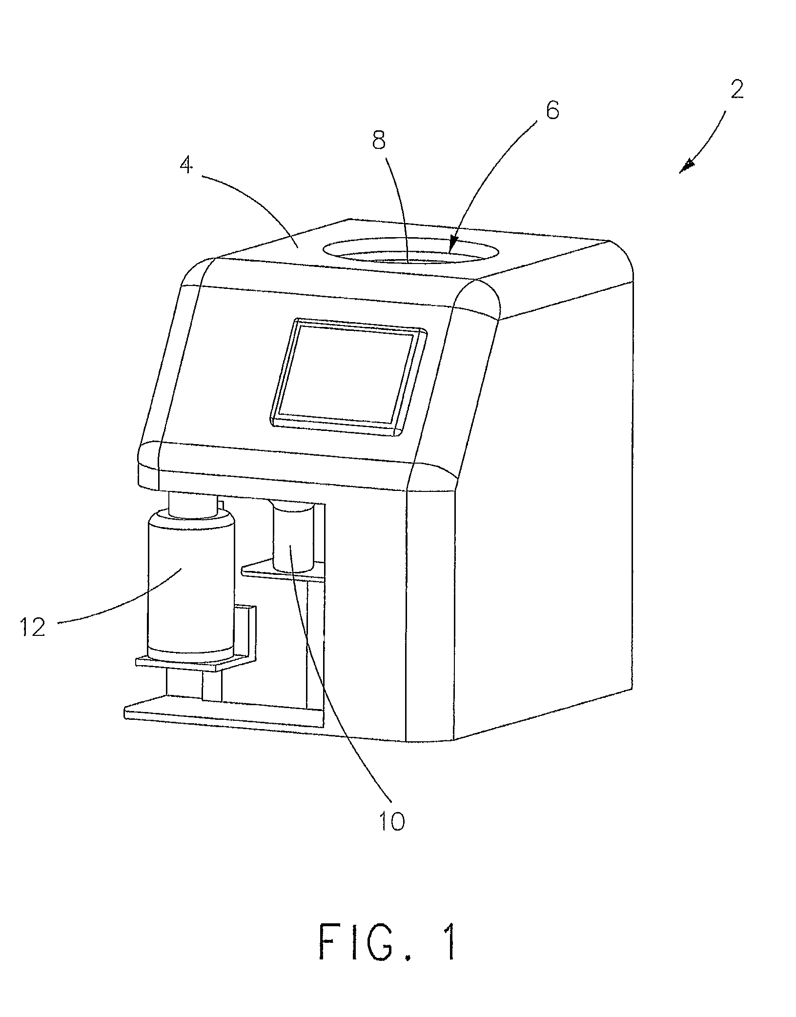
[0036]With reference to FIG. 1, a pill dispensing machine 2 includes a housing 4 haying an opening 6 in a top side of housing 4 for feeding pills (not shown) to a chute 8, either directly or via a hopper 9 (FIG. 4A), for processing and counting by pill dispensing machine 2 in a manner described hereinafter and for deposit of the counted pills into a pill bottle 10. Pills in excess of a desired number of pills to be dispensed into pill bottle 10 can be dispensed to a storage container 12.

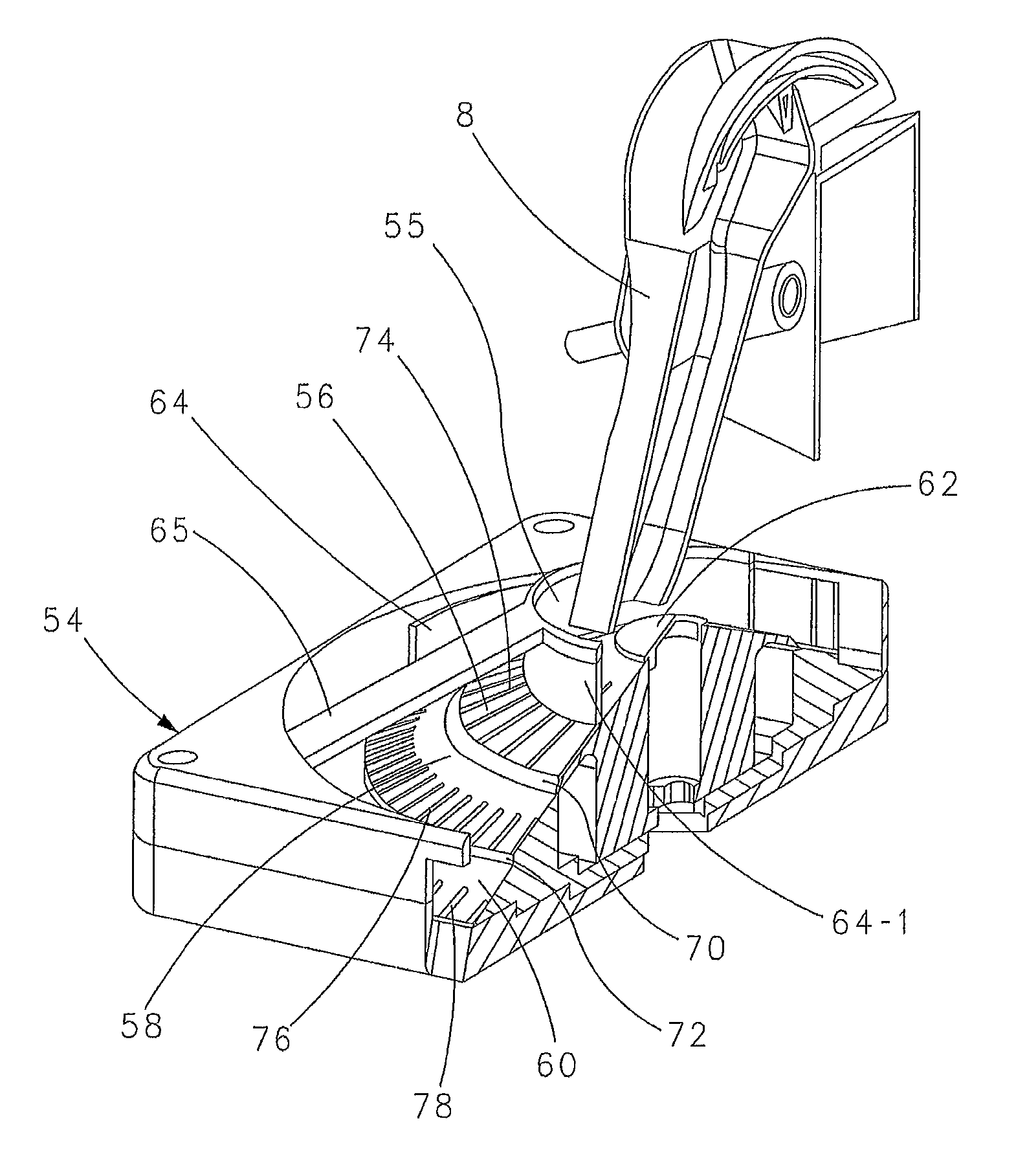
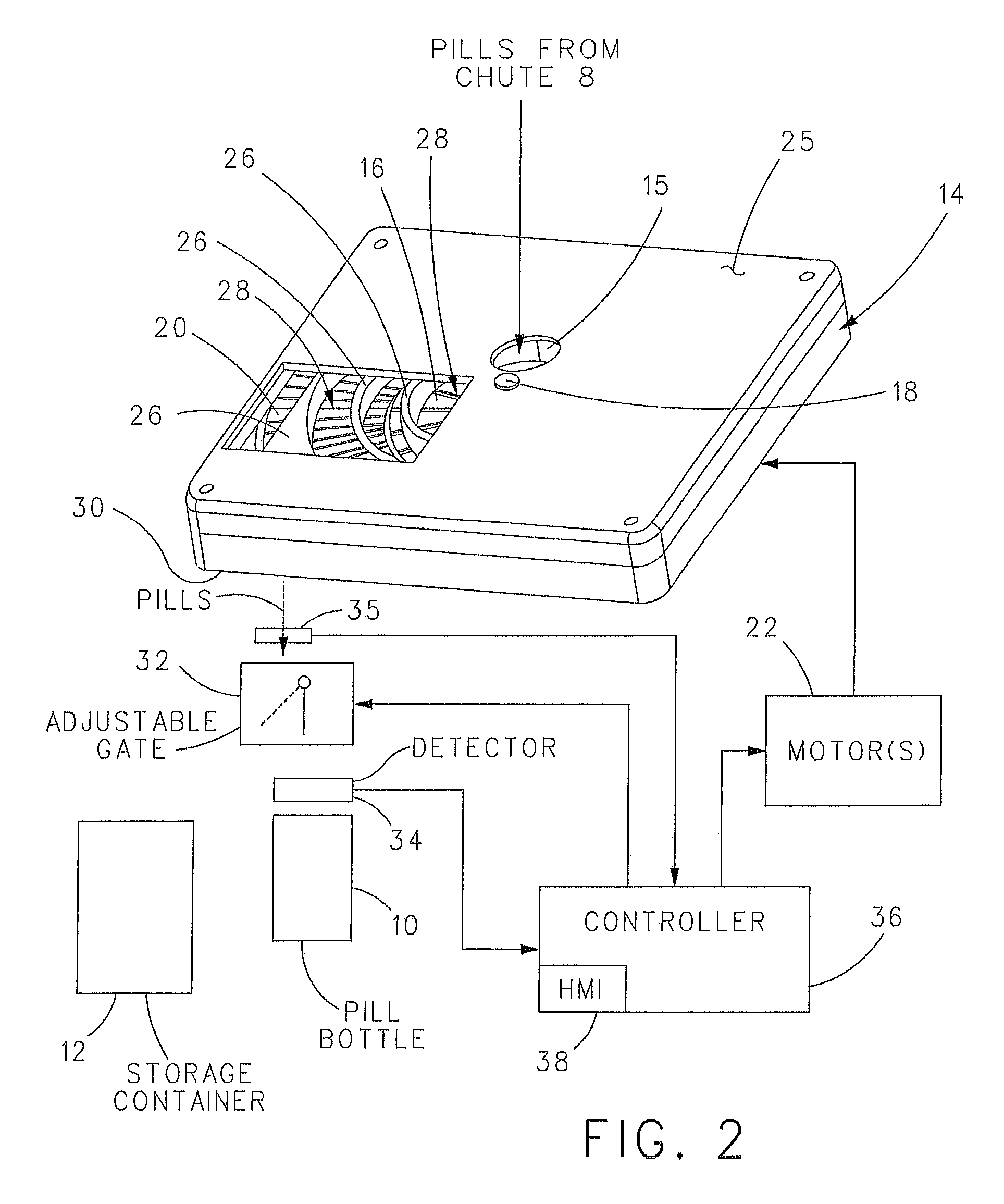
[0037]With reference to FIGS. 2 and 3 and with continuing reference to FIG. 1, pill dispensing machine 2 can include first embodiment cassette 14. In FIG. 2, a section of cassette 14 is shown removed for the purposes of illustration.

[0038]Cassette 14 includes a first rotor 16 disposed about a rotation axis 18 and a second rotor 20 disposed about first r...


PUM


Abstract

The present invention is a pill dispensing method and apparatus wherein a first rotor rotates pills about a rotation axis along a first part of a spiral path at a first rotational speed whereupon the pills move spirally away from the rotation axis. A second rotor receives the pills from the first rotor and rotates the pills about the rotation axis along a second part of the spiral path at a second, greater rotational speed whereupon the pills move spirally away from the rotation axis toward a discharge chute which dispenses the pills into a pill bottle or a storage container.

Description

CROSS REFERENCE TO RELATED APPLICATION[0001]This application claims priority from U.S. Provisional Patent Application No. 61 / 390,275, filed Oct. 6, 2010, which is incorporated herein by reference.BACKGROUND OF THE INVENTION[0002]Pharmacists routinely dispense solid medications following doctor's prescription. Most often they count the pills manually with the aid of a counting tray.[0003]In recent years various devices have come to the market intended to automate the counting process and ensure accuracy of the count. Unfortunately all of them either require human involvement in counting, are not accurate or safe enough, or cannot handle certain shapes or colors of the pills effectively.SUMMARY OF THE INVENTION[0004]A pill dispensing machine includes a hopper or chute into which pills to be counted are poured from a bulk container. A cassette inside the machine includes a plurality of rotors that move the pills along a spiral path. A gate incorporated into the path of pills exiting th...

Claims


Application Information

Patent Timeline
Patent Type & Authority Patents(United States)
IPC IPC(8): B65D83/04A61J7/02
CPCA61J7/02
Inventor CZARNEK, ROBERT
Owner CZARNEK & ORKIN LAB
Why Eureka
Try Eureka