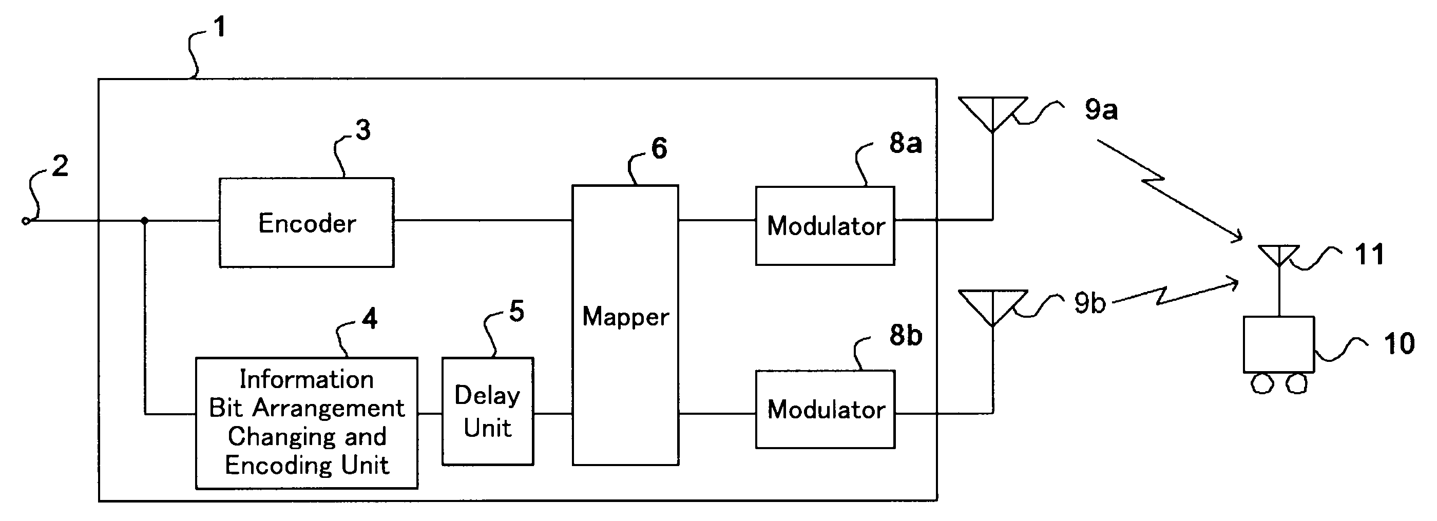
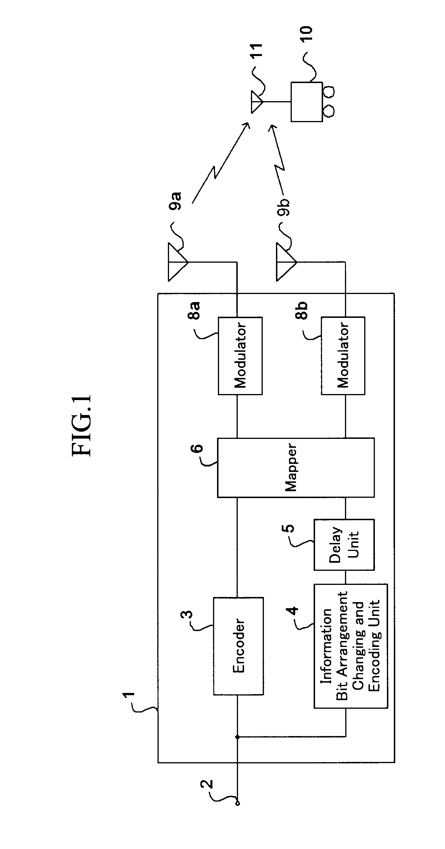
[0013]In accordance with the present invention, there is provided a radio
communication device which has two antennas and uses PADM (Per transmit Antenna Differential Mapping) transmission diversity of performing a different
differential phase shift modulation for each of the transmit antennas on signals created on a basis of an identical information sequence, and transmitting the signals, and which carries out a
demodulation process using PSP (Per-Survivor
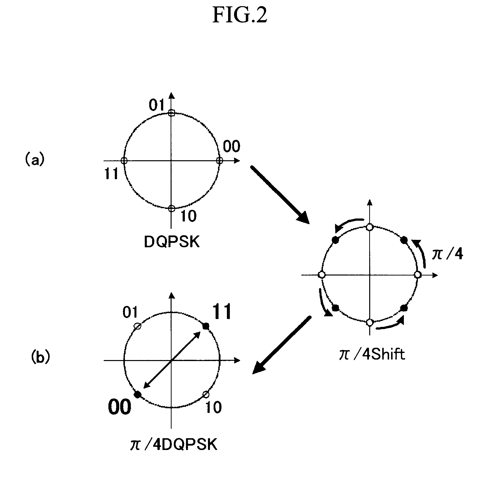
Processing), the radio communication device including: an encoding unit for performing an encoding process on an inputted information sequence for each of the transmit antennas; a delaying unit for delaying a transmission timing of a first one to be transmitted from one of the antennas, among information sequences which the encoding unit creates by encoding the inputted information sequence and which respectively correspond to the two antennas, with respect to a transmission timing of a second one of the information sequences to be transmitted from the other one of the antennas; a modulating unit for performing a π / 4-shift differential phase shift modulation process on the first information sequence, and for performing a differential phase shift modulation process on the second information sequence; a mapping unit for mapping each of the first and second information sequences onto a complex plane which consists of a real number axis and an imaginary number axis as signal points; and an information sequence arrangement changing unit for interchanging signal points respectively belonging to quadrants which are one of a first quadrant and a third quadrant, a second quadrant and a fourth quadrant, the first quadrant and the second quadrant, the first quadrant and the fourth quadrant, the second quadrant and the third quadrant, and the third quadrant and the fourth quadrant, the signal points being included in the signal points of the first information sequence mapped onto the complex plane, to change arrangement of the information sequence. As a result, even if the mapping of the DQPSK modulated signal (advance wave) is rotated, the mapping does not match the π / 4-shift DQPSK modulated signal (delayed wave). More specifically, because a receive side can discriminate between the advance wave and the delayed wave even when a
frequency deviation of 12.5% occurs in the DQPSK modulated signal which is the advance wave on the
transmission line, there is provided an
advantage of being able to avoid erroneous
estimation of the modulation method and the
frequency deviation, and being able to prevent a failure from occurring in the PSP
demodulation process performed by the receive side.
[0014]In accordance with the present invention, there is provided a radio communication device which has two antennas and uses PADM (Per transmit Antenna Differential Mapping) transmission diversity of performing a different differential phase shift modulation for each of the transmit antennas on signals created on a basis of an identical information sequence, and transmitting the signals, and which carries out a
demodulation process using PSP (Per-Survivor
Processing), the radio communication device including: an encoding unit for performing an encoding process on an inputted information sequence for each of the transmit antennas; a delaying unit for delaying a transmission timing of a first one to be transmitted from one of the antennas, among information sequences which the encoding unit creates by encoding the inputted information sequence and which respectively correspond to the two antennas, with respect to a transmission timing of a second one of the information sequences to be transmitted from the other one of the antennas; a modulating unit for performing a π / 8-shift differential phase shift modulation process on the first information sequence, and for performing a differential phase shift modulation process on the second information sequence; a mapping unit for mapping each of the first and second information sequences onto a complex plane which consists of a real number axis and an imaginary number axis as signal points; and an information sequence arrangement changing unit for interchanging the signal points of the first information sequence mapped onto the complex plane and signal points at positions which the information sequence arrangement changing unit acquires by performing an (n / 4)×π (n is an integer
ranging from 1 to 7)-shift differential phase shift modulation process on the signal points of the first information sequence to change arrangement of the information sequence. As a result, even if the mapping of the DQPSK modulated signal (advance wave) is rotated, the mapping does not match the π / 8-shift DQPSK modulated signal (delayed wave). More specifically, because a receive side can discriminate between the advance wave and the delayed wave even when a
frequency deviation of 6.25% occurs in the DQPSK modulated signal which is the advance wave on the
transmission line, there is provided an
advantage of being able to avoid erroneous
estimation of the modulation method and the frequency deviation, and being able to prevent a failure from occurring in the PSP demodulation process performed by the receive side.
[0015]In accordance with the present invention, there is provided a radio communication device which has two antennas and uses PADM (Per transmit Antenna Differential Mapping) transmission diversity of performing a different differential phase shift modulation for each of the transmit antennas on signals created on a basis of an identical information sequence, and transmitting the signals, and which carries out a demodulation process using PSP (Per-Survivor
Processing), the radio communication device including: an encoding unit for performing an encoding process on an inputted information sequence for each of the transmit antennas; a delaying unit for delaying a transmission timing of a first one to be transmitted from one of the antennas, among information sequences which the encoding unit creates by encoding the inputted information sequence and which respectively correspond to the two antennas, with respect to a transmission timing of a second one of the information sequences to be transmitted from the other one of the antennas; a modulating unit for performing a π / 4-shift differential phase shift modulation process on the first information sequence, and for performing a differential phase shift modulation process on the second information sequence; a mapping unit for mapping each of the first and second information sequences onto a complex plane which consists of a real number axis and an imaginary number axis as signal points; and an information sequence arrangement changing unit for interchanging signal points belonging to one of combinations including a combination of a signal point positioned on a positive real number axis and a signal point positioned on a negative real number axis, a combination of a signal point positioned on a positive imaginary number axis and a signal point positioned on a negative imaginary number axis, a combination of a signal point positioned on the positive real number axis and a signal point positioned on the positive imaginary number axis, a combination of a signal point positioned on the negative real number axis and a signal point positioned on the negative imaginary number axis, a combination of a signal point positioned on the positive real number axis and a signal point positioned on the negative imaginary number axis, and a combination of a signal point positioned on the negative real number axis and a signal point positioned on the positive imaginary number axis, among the signal points of the second information sequence mapped onto the complex plane, to change arrangement of the information sequence. As a result, even if the mapping of the DQPSK modulated signal (advance wave) is rotated, the mapping does not match the π / 4-shift DQPSK modulated signal (delayed wave). More specifically, because a receive side can discriminate between the advance wave and the delayed wave even when a frequency deviation of 12.5% occurs in the DQPSK modulated signal which is the advance wave on the transmission line, there is provided an
advantage of being able to avoid erroneous
estimation of the modulation method and the frequency deviation, and being able to prevent a failure from occurring in the PSP demodulation process performed by the receive side.
[0016]In accordance with the present invention, there is provided a radio communication device which has two antennas and uses PADM (Per transmit Antenna Differential Mapping) transmission diversity of performing a different differential phase shift modulation for each of the transmit antennas on signals created on a basis of an identical information sequence, and transmitting the signals, and which carries out a demodulation process using PSP (Per-Survivor Processing), the radio communication device including: an encoding unit for performing an encoding process on an inputted information sequence for each of the transmit antennas; a delaying unit for delaying a transmission timing of a first one to be transmitted from one of the antennas, among information sequences which the encoding unit creates by encoding the inputted information sequence and which respectively correspond to the two antennas, with respect to a transmission timing of a second one of the information sequences to be transmitted from the other one of the antennas; a modulating unit for performing a π / 8-shift differential phase shift modulation process on the first information sequence, and for performing a differential phase shift modulation process on the second information sequence; a mapping unit for mapping each of the first and second information sequences onto a complex plane which consists of a real number axis and an imaginary number axis as signal points; and an information sequence arrangement changing unit for interchanging the signal points of the second information sequence mapped onto the complex plane and signal points at positions which the information sequence arrangement changing unit acquires by performing an (n / 4)×π (n is an integer
ranging from 1 to 7)-shift differential phase shift modulation process on the signal points of the second information sequence to change arrangement of the information sequence. As a result, even if the mapping of the DQPSK modulated signal (advance wave) is rotated, the mapping does not match the π / 8-shift DQPSK modulated signal (delayed wave). More specifically, because a receive side can discriminate between the advance wave and the delayed wave even when a frequency deviation of 6.25% occurs in the DQPSK modulated signal which is the advance wave on the transmission line, there is provided an advantage of being able to avoid erroneous estimation of the modulation method and the frequency deviation, and being able to prevent a failure from occurring in the PSP demodulation process performed by the receive side.

