Frequency modulation radar apparatus for vehicle use background of the invention

Inactive Publication Date: 2008-05-29
MITSUBISHI ELECTRIC CORP
View PDF18 Cites 6 Cited by
  • Summary
  • Abstract
  • Description
  • Claims
  • Application Information

AI Technical Summary

Benefits of technology

[0018]According to the present invention, a true peak value can be made to coincide with a peak value of a d

Problems solved by technology

Here, if the frequency resolution 1/T is to be set to a small value so as to detect the target object X with a high degree of precision, the observation time T will naturally increase and the processing time will also increase, and hence this is not desirable.
In the conventional frequency modulation radar apparatus for vehicle use, in actuality, there exists noise resulting mainly from thermal noise, so the signal strengths an−1, an, an+1 of the discrete spectrum obtained by fast Fourier transform become different from the values theoretically predicted, an

Method used


Image

  • Frequency modulation radar apparatus for vehicle use background of the invention
  • Frequency modulation radar apparatus for vehicle use background of the invention
  • Frequency modulation radar apparatus for vehicle use background of the invention

Examples


Example

Embodiment 1

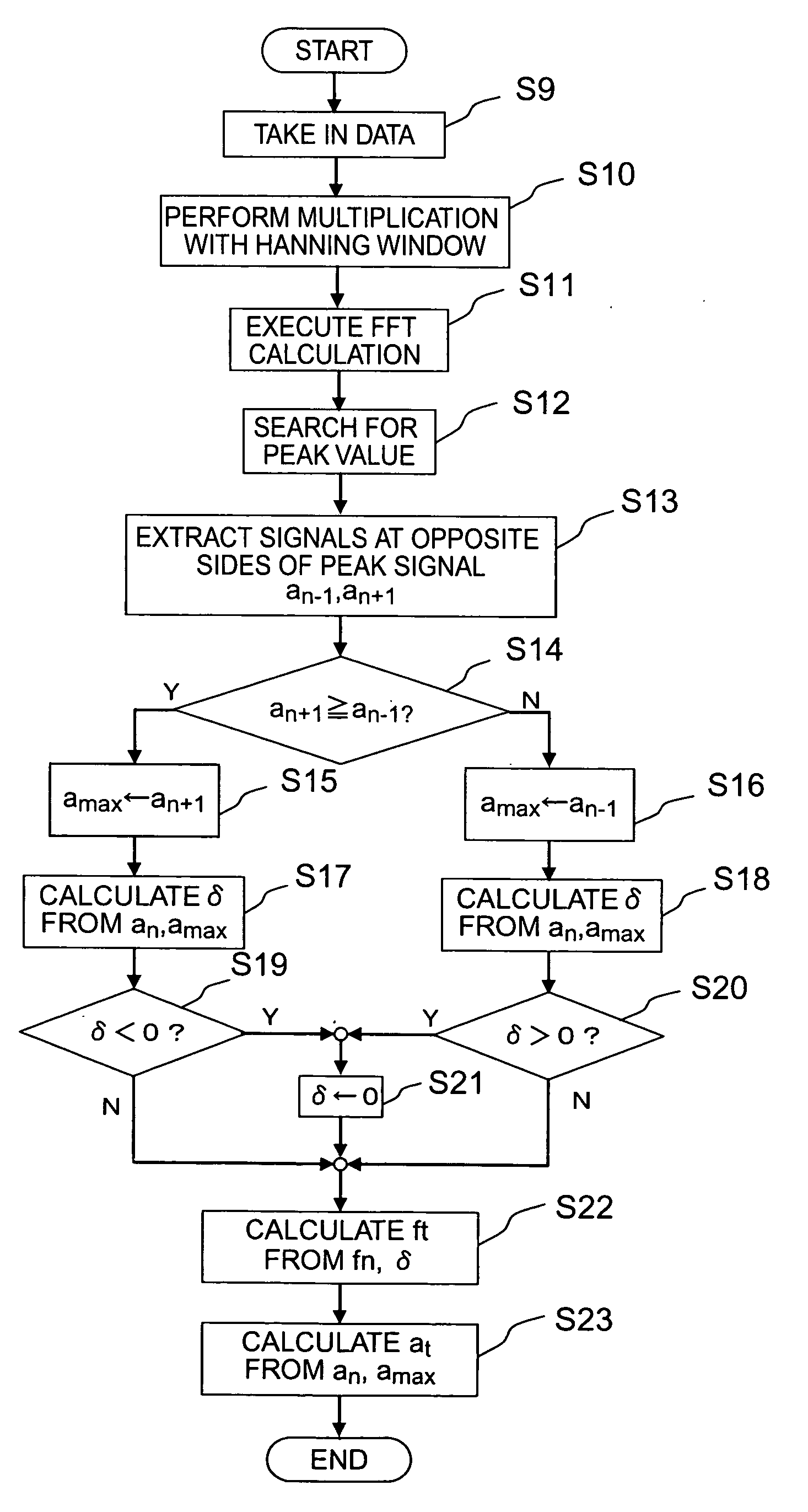
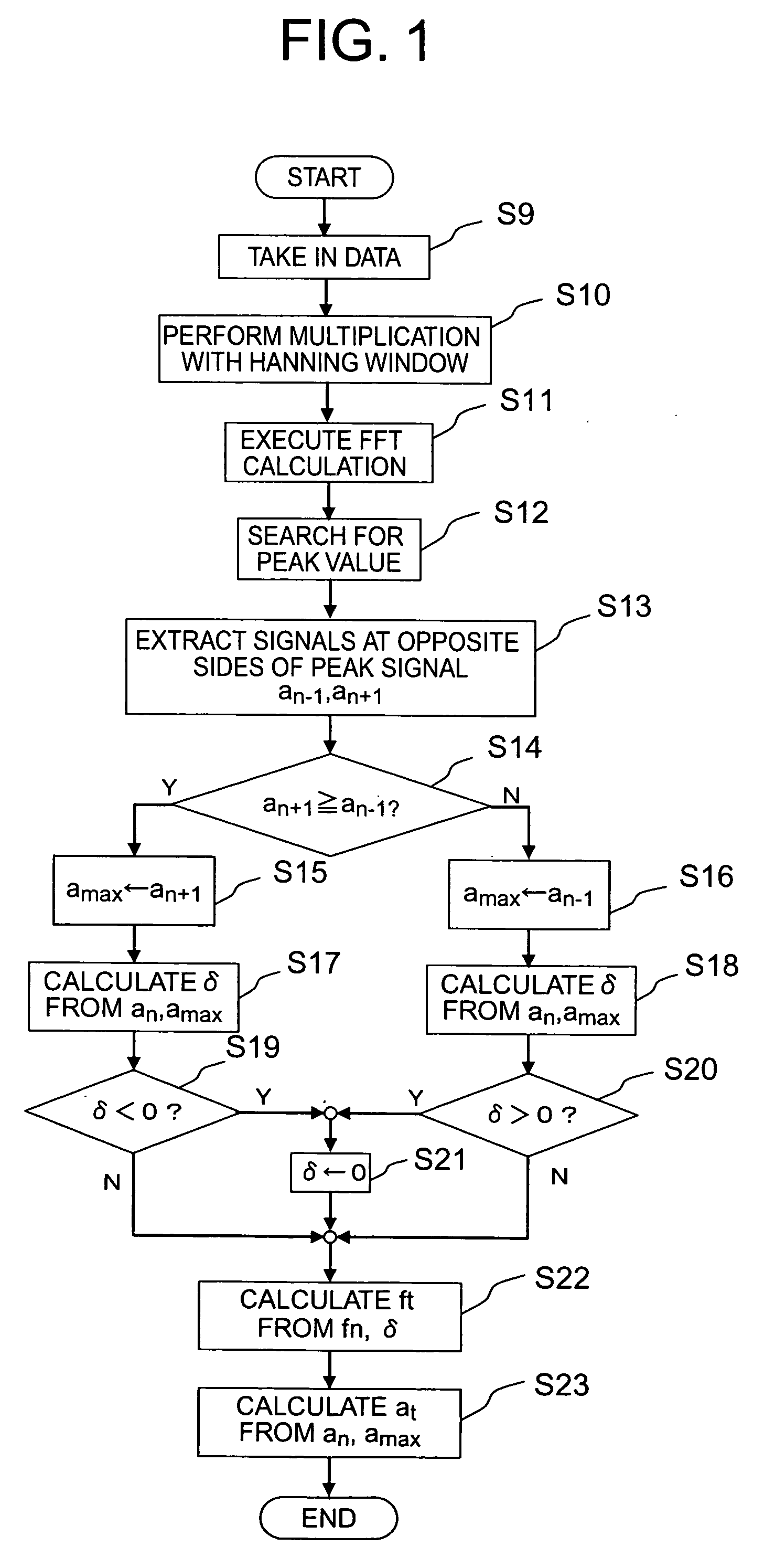
[0030]Referring to the drawings and first to FIG. 1, there is shown a flow chart that illustrates FFT calculation processing by a frequency modulation radar apparatus for vehicle use according to a first embodiment of the present invention. Here, note that the construction of the frequency modulation radar apparatus for vehicle use according to the first embodiment of the present invention is similar to that of the above-mentioned conventional apparatus (see FIG. 8), but is only different therefrom in a part of the calculation processing of the frequency fn and the strength an of a peak signal in an FFT calculation section 8.

[0031]In addition, the operation of the frequency modulation radar apparatus of this invention until a sampled beat signal is input to the FFT calculation section 8 and the processing operation of a CPU 1 are similar to those as stated before, and hence a detailed explanation thereof is omitted here.

[0032]In this case, the FFT calculation section 8 (...

Example

[0068]Although in the above-mentioned first embodiment, the strength at of the true peak signal is calculated by using the expression (3), an approximate expression comprising the following expression (4) may be used so as to simplify (i.e., speed up) the arithmetic calculation.

at=0.81an+0.35amax   (4)

[0069]In the above expression (4), individual coefficients “0.81”, “0.35” are the values that are set to minimize the absolute value of a strength error on the assumption that a linear combination of individual strengths an, an+1 is taken as the strength at of the true peak signal (in case of a+1≧an−1).

[0070]Here, reference will be made to the effectiveness of the expression (4) while referring to an explanatory view of FIG. 2.

[0071]When the strength an is used as it is as the strength at of the true peak signal, a strength error, indicated by an alternate long and short dash line in FIG. 2, will occur in accordance with the amount of frequency correction δ, so the strength at of the t...

Example

Embodiment 2

[0081]Although in the above-mentioned first embodiment, an additive correction of the amount of frequency correction δ is used to calculate the frequency ft of the true peak signal, the frequency ft of the true peak signal may be calculated by using a strength amax of one of the strengths an−1, an+1 which is not smaller than the other and a frequency fmax corresponding to the strength amax based on a linear combination of the frequency fn of the peak signal and the frequency fmax.

[0082]Hereinafter, reference will be made to a frequency modulation radar apparatus for vehicle use according to a second embodiment of the present invention while referring to a flow chart in FIG. 3 together with FIGS. 8 and 9.

[0083]In this case, a frequency correction section in an FFT calculation section 8 calculates a frequency ft of a true peak signal based on a linear combination of a frequency fn of a peak signal and an under-mentioned frequency fmax, by using a strength an of the peak si...


PUM


Abstract

A frequency modulation radar apparatus for vehicle use can suppress the influence of noise to avoid incorrect estimation due to noise thereby to provide a beat frequency with high accuracy and at high speed without increasing the frequency resolution of the beat frequency that causes an increase in an observation time. The apparatus includes a frequency correction section that calculates a corrected frequency (fn+δ) by adding an amount of frequency correction (δ) to the frequency (fn) of a peak signal, and a CPU that calculates a distance or a relative speed to a target object based on the corrected frequency (fn+δ). In an FFT calculation section, the frequency (ft) of the true peak signal is calculated based on the characteristic of a window function, and if the frequency (ft) thus calculated is determined as an incorrect estimation, the frequency of the true peak signal is further corrected.

Description

BACKGROUND OF THE INVENTION[0001]1. Field of the Invention[0002]The present invention relates to a frequency modulation radar apparatus for vehicle use which is installed on a motor vehicle for measuring the distance, the relative speed, etc., to a neighboring vehicle for the purpose of being used for vehicle-to-vehicle distance control, collision damage reduction, etc.[0003]2. Description of the Related Art[0004]Conventionally, there has been well known a frequency modulation radar apparatus for vehicle use which sends a transmission signal the frequency of which is frequency modulated so as to linearly rise or fall in accordance with the elapse of time, receives the signal reflected by a target object, samples a beat signal that is obtained by mixing the reception signal thus received with the transmission signal, performs a discrete frequency analysis by using a predetermined window function, extracts a peak signal from the spectrum of a beat signal thus obtained, and calculates ...

Claims


Application Information

Patent Timeline
IPC IPC(8): G01S13/02G01S13/931
CPCG01S7/354G01S13/34G01S2013/9325G01S13/931G01S2007/356G01S13/345G01S7/356
Inventor NODA, SHINSAKU
Owner MITSUBISHI ELECTRIC CORP
Why Eureka
Try Eureka