Supercharge Your Innovation With Domain-Expert AI Agents!

Drive device of a marine acoustic vibrator

A vibrator, seismic vibrator technology, applied in the field of marine geophysical exploration, can solve problems such as limited use and limited use

Inactive Publication Date: 2009-09-09
PGS GEOPHYSICAL AS
View PDF0 Cites 2 Cited by
  • Summary
  • Abstract
  • Description
  • Claims
  • Application Information

AI Technical Summary

Problems solved by technology

However, these sources are of limited use
Although these sources emit signals in different frequency bands (commonly referred to as "sweeps"), it is known in the art that the limited power these sources can produce limits their usefulness in offshore operations

Method used

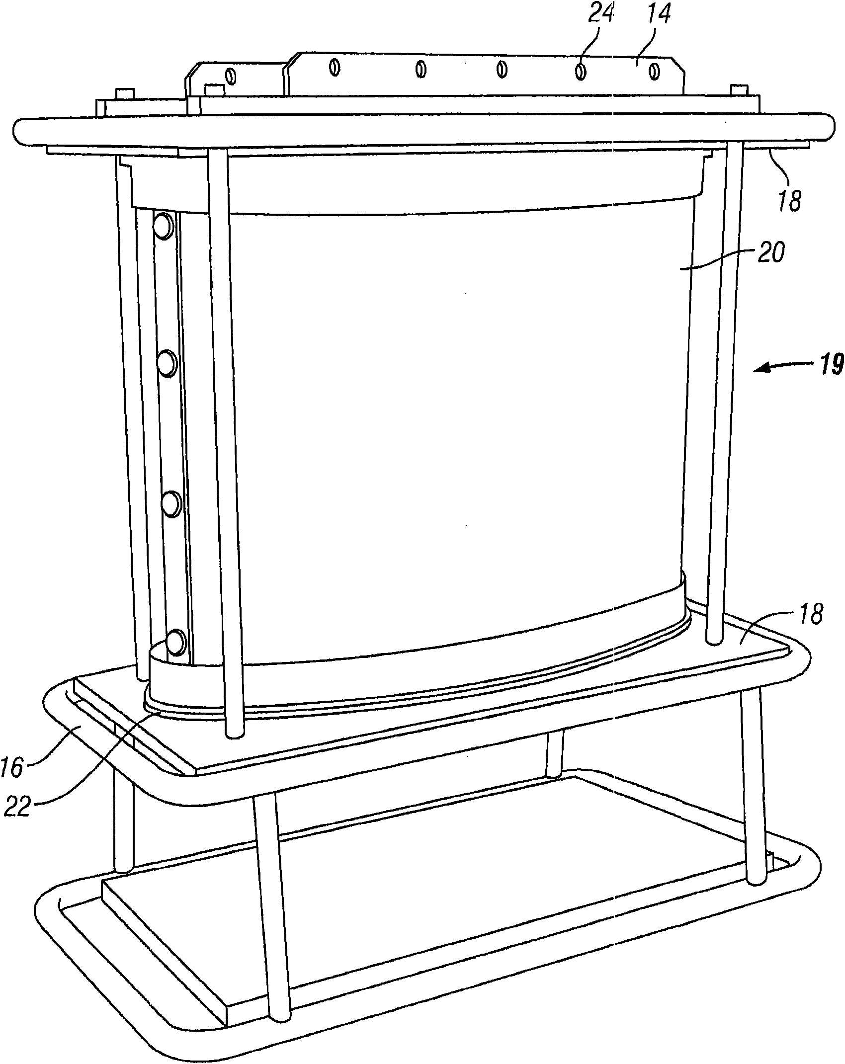
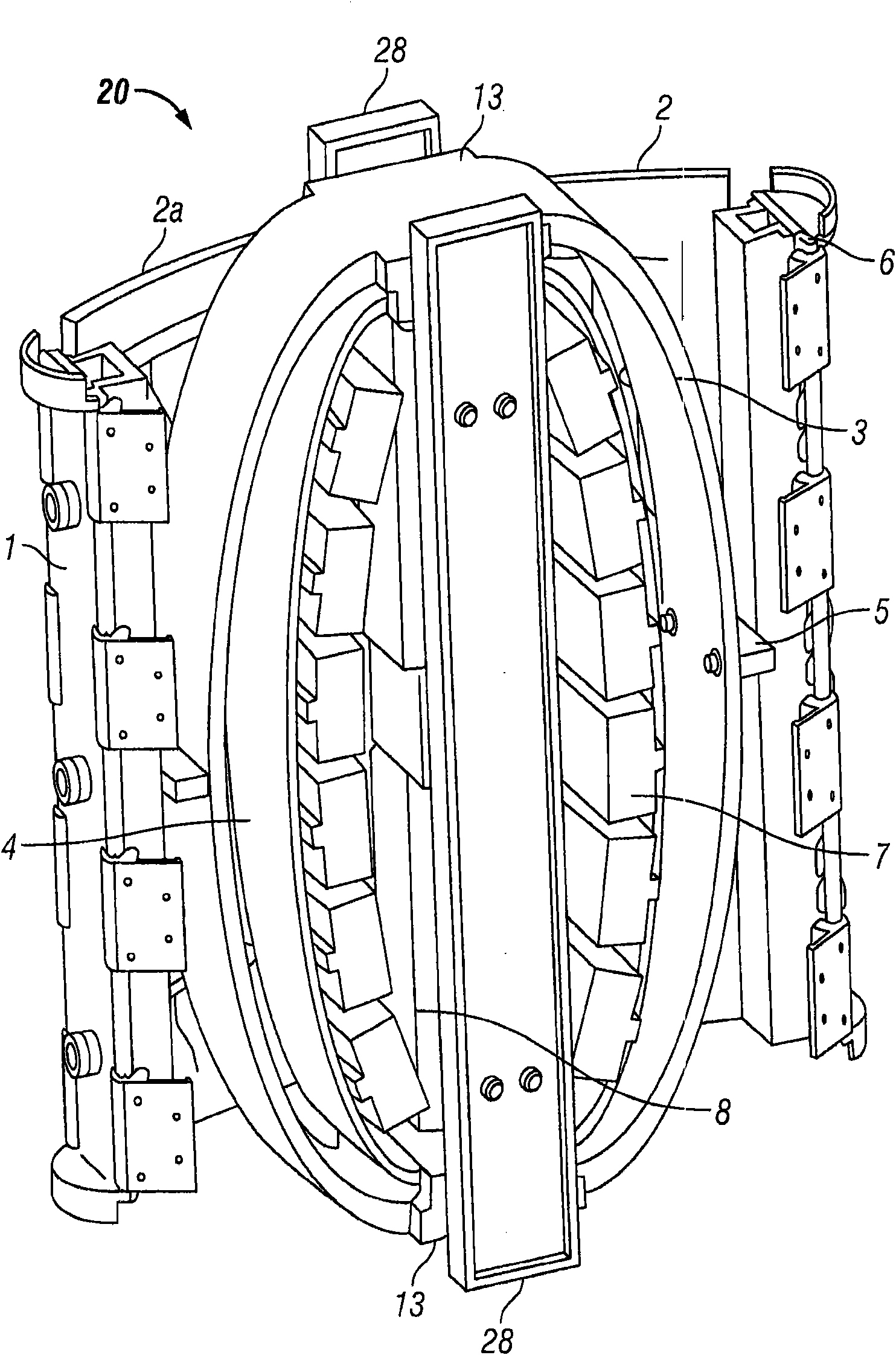
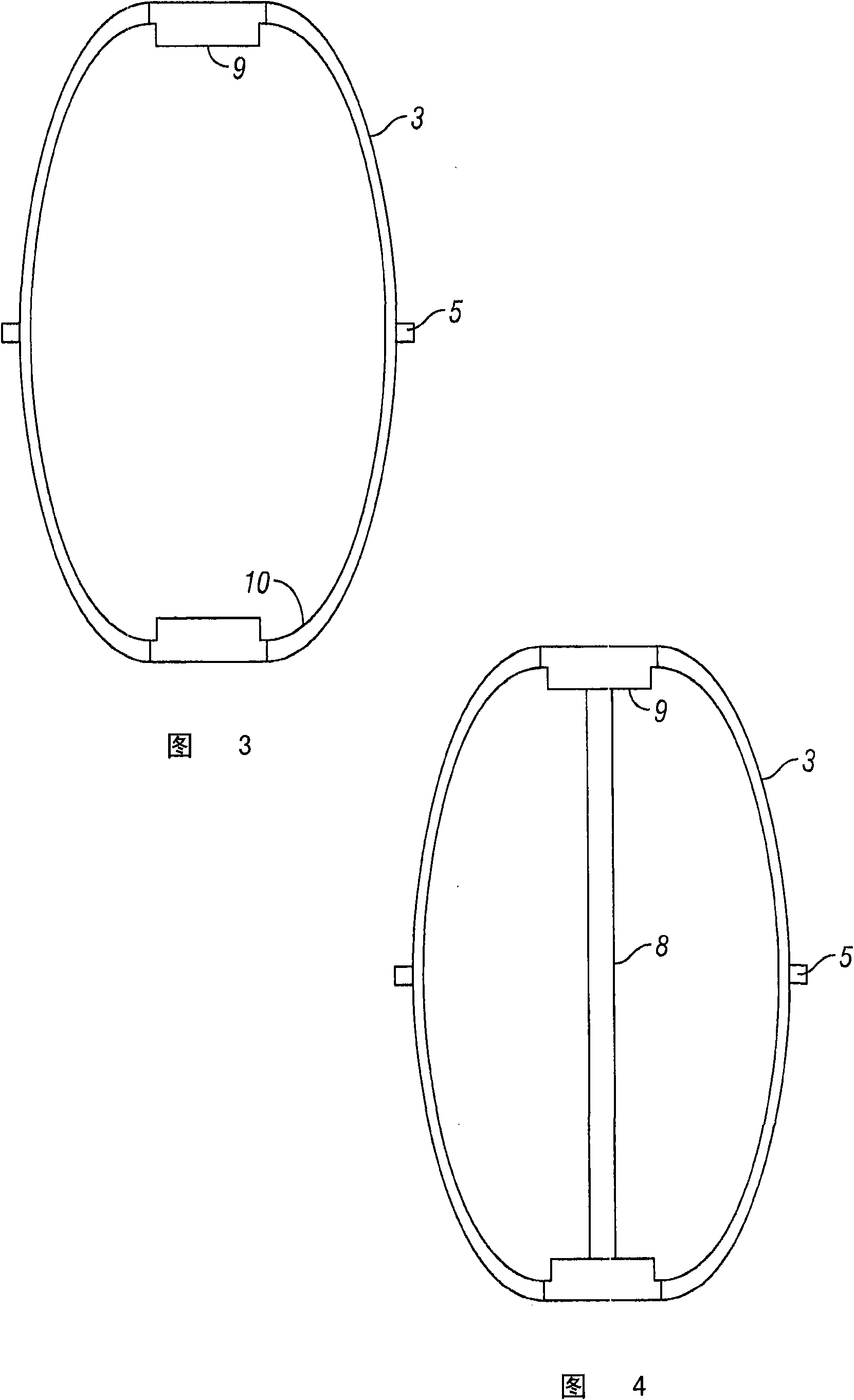

Image

  • Drive device of a marine acoustic vibrator
  • Drive device of a marine acoustic vibrator
  • Drive device of a marine acoustic vibrator

Examples


Embodiment Construction

[0013] The total impedance experienced by the marine vibrator can be expressed as follows:

[0014] Z r = R r +jX r (equation 1)

[0015] in

[0016] Z r is the total impedance

[0017] R r is the radiation impedance, and

[0018] x r is the reaction impedance.

[0019] When analyzing the energy transfer of marine vibrators, the system can be approximated as a baffled piston. When expressing the total impedance to be experienced, the radiation impedance R of the barrier piston r for:

[0020] R r = πa 2 ρ 0 c 1 (x) (Equation 2)

[0021] And the reaction impedance is:

[0022] x r = πa 2 ρ 0 wxya 1 (x) (Equation 3)

[0023] in

[0024] x = 2 ka = 4 πa λ = 2 ωa c (equation 4)

[0025] ...


PUM


Abstract

The present invention relates to a drive device of a marine acoustic vibrator. The marine vibrator that in a particular embodiment includes a substantially elliptically shaped outer shell, a driver having a first and second end, at least one outer spring connected between the first end and the second end of the driver, and at least one inner spring connected between the first end and the second end of the driver. One or more masses are attached to the inner spring. At least one transmission element connects the outer spring and the outer shell. The outer and inner springs and the masses attached to the inner spring are selected to generate a first resonance frequency and a second resonance within the frequency range between 1 Hz and 300 Hz.

Description

technical field [0001] This invention relates to marine geophysical prospecting, and more particularly to vibratory sources for marine geophysical prospecting. Background technique [0002] Seismic sources, including vibratory sources, are used in geophysical surveys of land and water covered areas of the Earth. Signals from these sources travel down into the earth, are reflected from reflective interfaces in the subsurface and are detected by signal detectors (usually hydrophones or geophones) on or near the earth's surface. [0003] Most sound sources used in offshore operations today are of the pulse type, in which an effort is made to generate as much energy as possible in the shortest possible time interval. The spectrum of such sources can only be controlled to a small extent, and different sources are chosen to produce different frequency ranges for different survey needs. Vibroacoustic sources have been used in offshore operations, including hydraulically driven so...

Claims


Application Information

Patent Timeline
Patent Type & Authority Applications(China)
IPC IPC(8): G01V1/143G01V1/38
CPCG10K9/121G01V1/145
Inventor S·R·L·滕汉恩
Owner PGS GEOPHYSICAL AS
Features
  • R&D
  • Intellectual Property
  • Life Sciences
  • Materials
  • Tech Scout
  • Unparalleled Data Quality
  • Higher Quality Content
  • 60% Fewer Hallucinations
Learn More