
Eureka
For R&D, Eureka makes reading and utilizing patents & technical documents easy.
Eureka AIR
Designed for self-driven R&D workflows. Generate viable solutions, solve complex R&D challenges, empower your innovation with AI.

Eureka Materials
Designed for material experts only. Revolutionize your material R&D, from search, analyze, to developing new materials.

TechResearch
Generate reliable direction feasibility study reports for your R&D in just a few steps.

TechSeek
Discover and master advanced knowledge NOW. Basics, ideas, possibilities, all at once.

TechMind
As an expert in R&D Theories, TechMind can generates customized viable solutions instantly.

TechRisk
Analyze your overall solution with one click, know your potential R&D risks in advance.

TechMonitor
Get weekly tech updates, stay abreast of the latest tech innovations and key insights.
Electronic device system and control method in electronic device system
An electronic equipment system, equipment technology, applied in the direction of the equipment of the electric recording process applying the charge pattern, the electric recording process applying the charge pattern, the electric recording technique, etc.
- Summary
- Abstract
- Description
- Claims
- Application Information
AI Technical Summary
Problems solved by technology
Method used
Image


Examples
no. 1 Embodiment approach
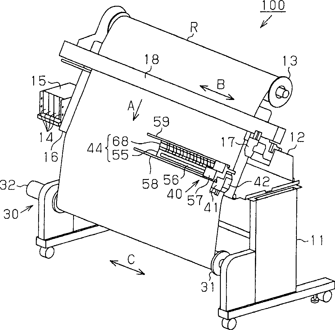
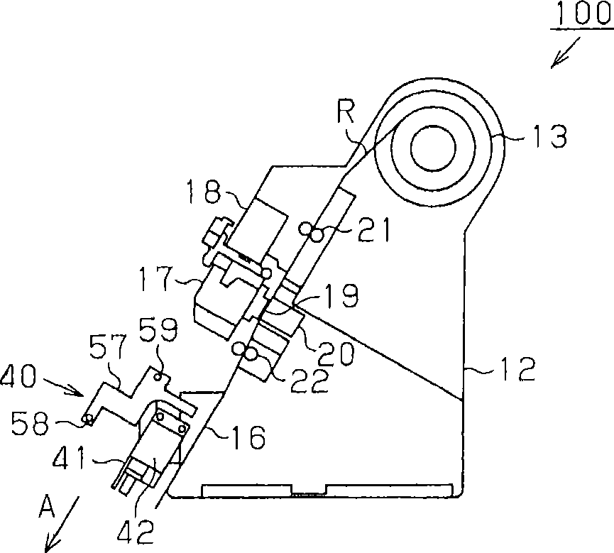
[0037]Below, according to Figure 1 to Figure 14 The first embodiment that actualizes the present invention will be described. figure 1 It is a perspective view showing an inkjet printer with an exterior case removed. in addition, figure 2 Shows a side sectional view of the main part of the printer.
[0038] as figure 1 The printer system 100 of the electronic equipment system shown is, for example, a printer 10 as a large-sized inkjet printer capable of performing recording on a large sheet of paper, a roll paper for winding printing performed by the printer 10, ) R winding device 30 and a color measuring device 40 for measuring the color of the color patch printed on the roll recording paper R by the printer 10 . As the target (recording medium), that is, paper, not only roll recording paper R but also single sheets of paper may be used.
[0039] printer 10 such as figure 1 As shown, a roll-type recording paper holder 13 is provided on the upper part of the rear part ...
no. 2 Embodiment approach
[0179] Below, according to Figure 15 to Figure 25 A second embodiment of the present invention will be described.
[0180] Figure 15 It is a block diagram showing an electrical configuration of a printing system including the printer system 100 of the second embodiment. In addition, since all of the plurality of printer systems 100 have the same configuration, only one configuration is shown.
[0181] The printing system 200 is the same as the first embodiment, and includes the printer system 100 and the host device 150 connected in a communicable state with the printer system 100 . Main device 150 is constituted by, for example, a personal computer or the like. The host device 150 incorporates, for example, a first printer driver 151 (host driver) constructed by installing printer driver software. The communication unit 152 of the host device 150 and the communication unit 74 of the printer 10 constituting the printer system 100 are connected via a communication cable. ...
PUM
 Abstract
Description
Claims
Application Information
 - R&D Engineer
- R&D Manager
- IP Professional
- Industry Leading Data Capabilities
- Powerful AI technology
- Patent DNA Extraction
Browse by: Latest US Patents, China's latest patents, Technical Efficacy Thesaurus, Application Domain, Technology Topic, Popular Technical Reports.
© 2024 PatSnap. All rights reserved.Legal|Privacy policy|Modern Slavery Act Transparency Statement|Sitemap|About US| Contact US: help@patsnap.com