Air purifier

An air purification device and air technology, applied in the field of air purification, can solve the problems of clogging the filter, the filter cannot be fully removed, and the maintenance work requires labor and cost.

Inactive Publication Date: 2009-09-16
MISAWA HOMES CO LTD +1
View PDF3 Cites 35 Cited by
  • Summary
  • Abstract
  • Description
  • Claims
  • Application Information

AI Technical Summary

Problems solved by technology

[0004] However, when air is continuously ingested with a filter-equipped ventilator, dust can clog the filter
Therefore, it is necessary to clean or replace the filter, and this maintenance work requires manpower and cost
In addition, NO in the air cannot be sufficiently removed by the filter x , SO x , NH 4 and other gases and gases as a source of malodour, while NO x , SO x , NH 4 When the gas is ingested into the residence

Method used


Image

  • Air purifier
  • Air purifier
  • Air purifier

Examples


no. 1 approach

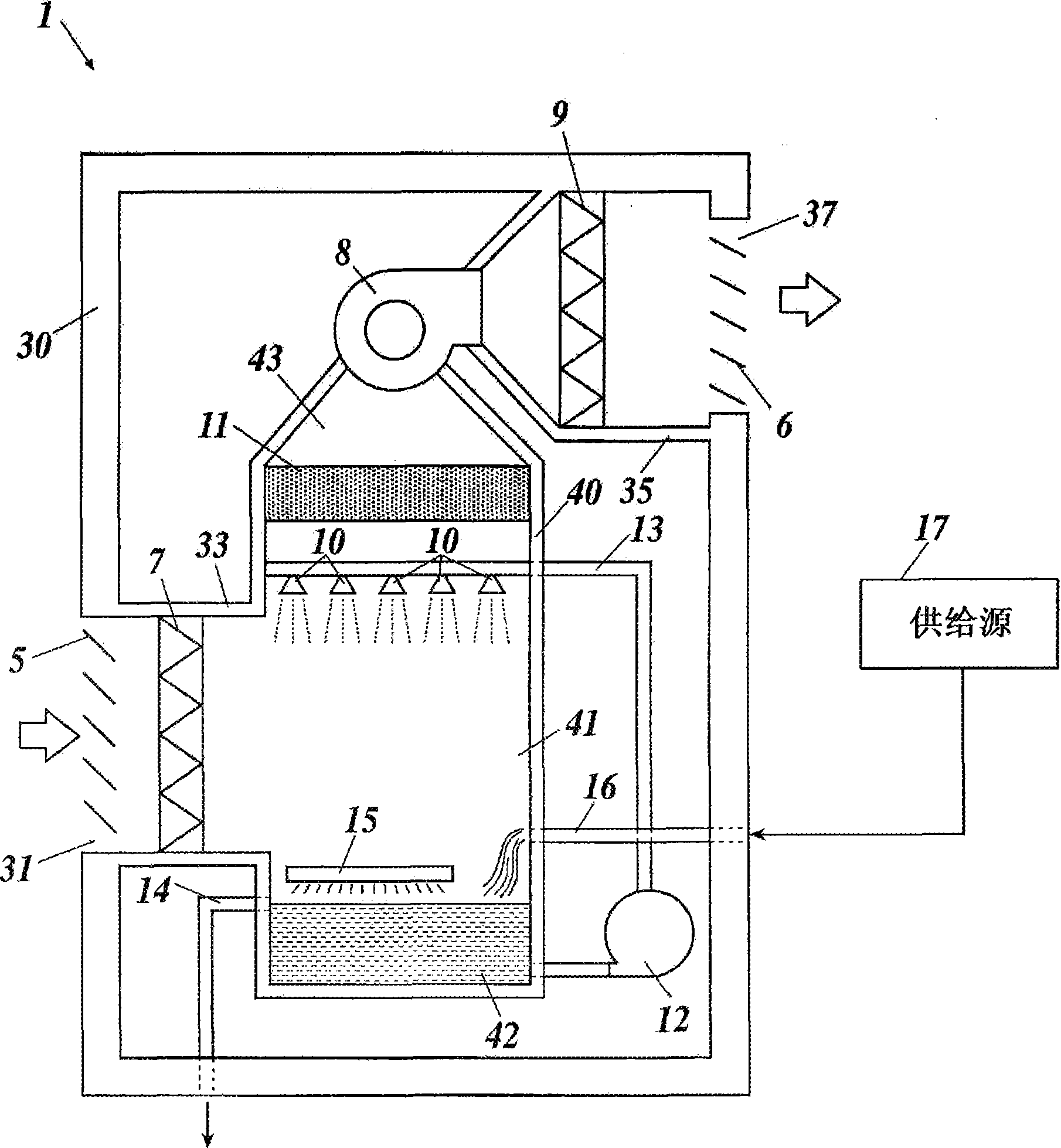
[0024] figure 1 It is a longitudinal sectional view of the air cleaner 1 . This air cleaner 1 is installed in a house, and air outside the house is taken into the house by the air cleaner 1 .

[0025] Such as figure 1 As shown, the housing 30 has a space formed therein. An intake port 31 is formed at the lower portion of the side surface of the housing 30 , and an exhaust port 37 is formed at the upper portion of the side surface of the housing 30 . The air intake port 31 is provided with a louver 5 , and the exhaust port 37 is also provided with a louver 6 . The suction port 31 is exposed to the outside of the house, or communicates with the outside of the house through a pipe.

[0026] The inside of the casing 30 is provided with a suction pipe 33 , an exhaust pipe 35 and a cleaning tower 40 . The cleaning tower 40 is provided in a vertically elongated shape, and an internal space is formed inside the cleaning tower 40 . The upper and lower middle part of the inner spa...

no. 2 approach

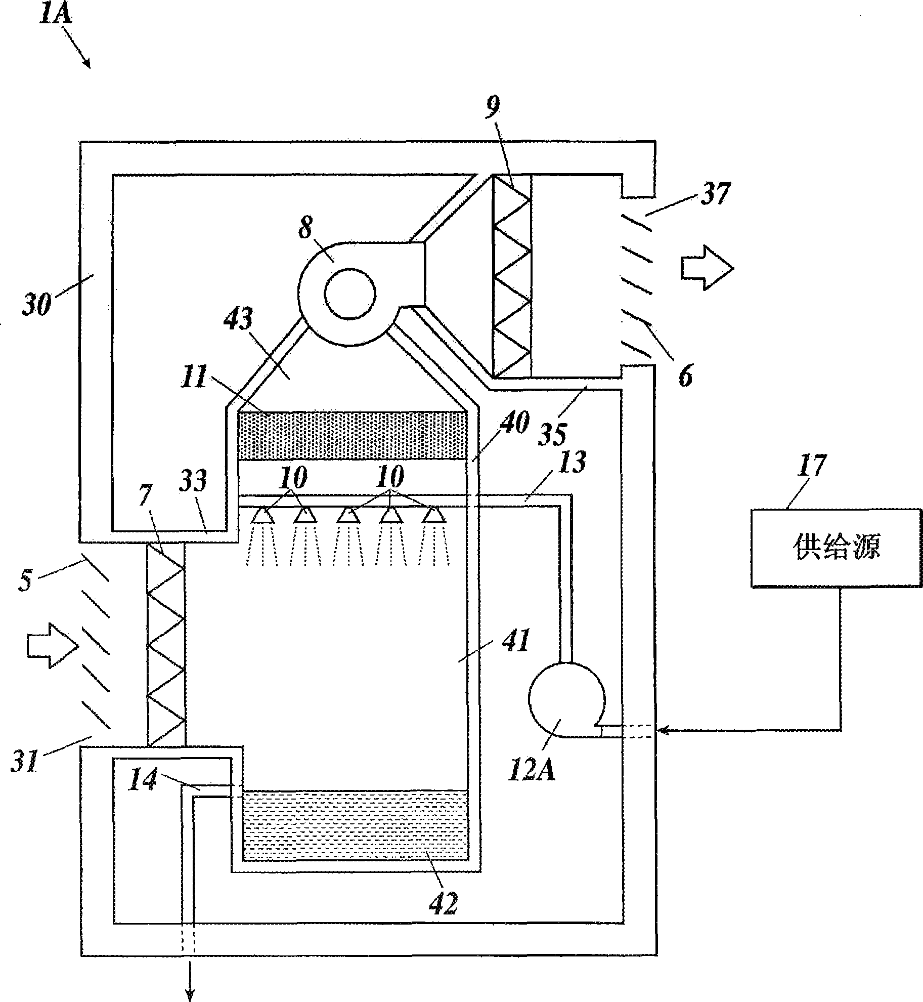
[0059] In the air cleaner 1 of the first embodiment, the water in the drainage ditch 42 is sucked out by the pressure pump 12 and pressure-fed to the nozzle 10 . In contrast, in the second embodiment, as figure 2 Like the shown air cleaner 1A, the water from the supply source 17 may be sucked out by the pressure pump 12A and pressure-fed to the nozzle 10 . Therefore, water is not circulated in this air cleaning device 1A, and the water sprayed in mist form from the nozzle 10 and stored in the drain 42 is discharged through the drain pipe 14 . In addition, since water does not circulate in this air cleaning device 1A, no sterilizing device is installed in the above-mentioned cleaning tower 40 .

[0060]In addition to the above-mentioned structure, this air cleaning device 1A is set in the same way as the air cleaning device 1 of the first embodiment. The parts are marked with the same symbols. Also in this air cleaning device 1A, the air sent into the house can be cleaned a...

no. 3 approach

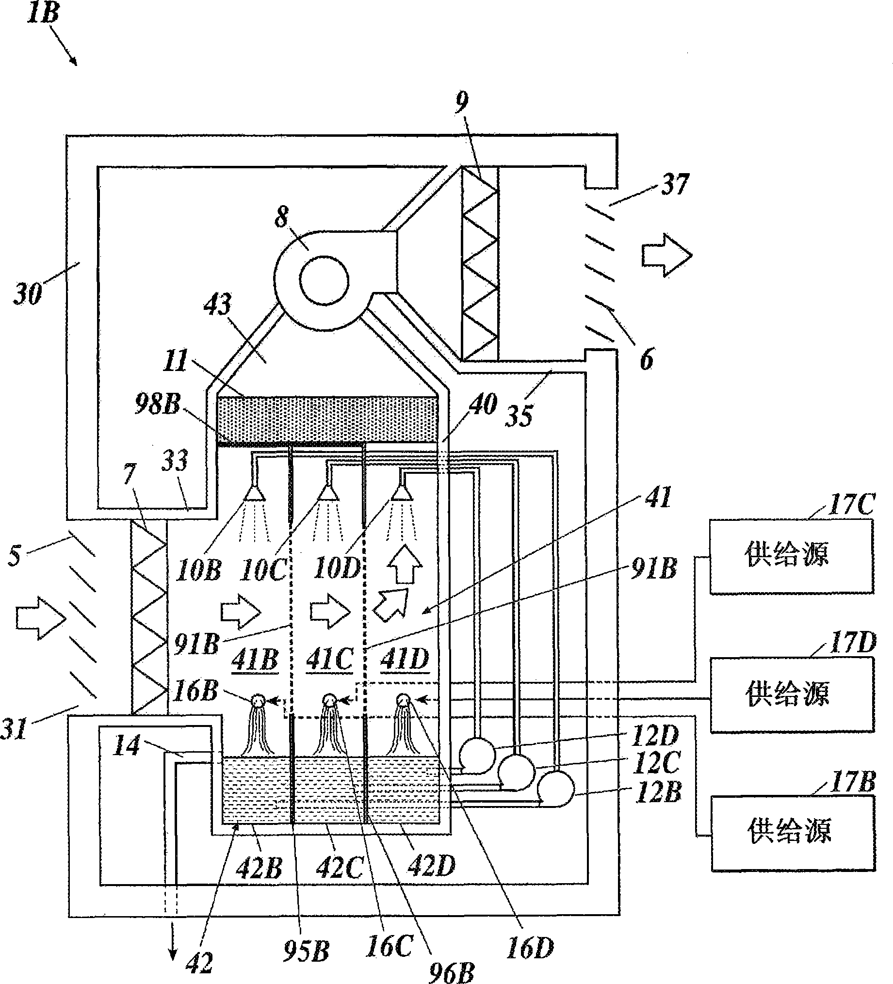
[0062] In the third embodiment, if image 3 In the shown air cleaner 1B, the spray chamber 41 is divided into three chambers 41B, 41C, 41D by nets 91B, 92B, and the drain 42 is divided into three chambers 42B, 42C, 42D by partition walls 95B, 96B. Here, the mesh 91B is connected to the partition wall 95B, and the mesh 92B is connected to the partition wall 96B. Mesh 91B partitions chamber 41B from chamber 41C, mesh 92B partitions chamber 41C from chamber 41D, partition wall 95B partitions chamber 42B from chamber 42C, and partition wall 96B partitions chamber 42C from chamber 42D. The duct 33 communicates with the chamber 41B on the opposite side of the chamber 41C. The upper sides of the chamber 41B and the chamber 41C are closed by the partition wall 98B, and the upper side of the chamber 41D is open, and the chamber 41D communicates with the exhaust chamber 43 via the water eliminator 11 .

[0063] In addition, the chamber 41B and the chamber 42B are vertically connected,...


PUM

PropertyMeasurementUnit
diameteraaaaaaaaaa
lengthaaaaaaaaaa

Abstract

An air purifier comprises a cleaning tower having an internal space communicating with a suction port and a discharge port, a blower for taking air from the suction port into the internal space of the cleaning tower and send it from the discharge port to the outside of the cleaning tower, and nozzles disposed in the internal space of the cleaning tower and spraying water in the internal space of the cleaning tower. The water sprayed from the nozzles is brought into contact with the air supplied by the blower in the cleaning tower.

Description

technical field [0001] The present invention relates to an air purifying device, in particular to a technology for purifying the air sent into houses and the like. Background technique [0002] Conventionally, a ventilator is installed in a house, and air is taken into the house by the ventilator to ventilate the house. However, in the air containing NO x , SO x , NH 4 Such substances as gas and dust are also taken into the house through the ventilation device. In order to remove dust, a house is provided with a ventilator equipped with a filter, and the filter collects the dust to take in purified air into the house (for example, Japanese Laid-Open Patent Publication No. 2003-21375). [0003] In addition, as an air purifying device using water without using a filter, there is a water storage type air purifying device. The water storage type air cleaning device is a device that stores a certain amount of water at the bottom of the water tank and blows air into the water...

Claims


Application Information

Patent Timeline
Patent Type & Authority Applications(China)
IPC IPC(8): F24F7/00A61L9/14B01D61/02B01D61/48C02F1/32C02F1/42C02F1/44C02F1/46C02F1/469
CPCB01D2257/404A61L9/14B01D47/06B01D2257/302C02F2103/18B01D2257/406C02F1/32C02F1/4672B01D47/14B01D53/78B01D53/18C02F1/441B01D61/02B01D61/48F24F8/133F24F8/30
Inventor 浅野正彦八木仁山中弘次铃木阳代藤田雅司
Owner MISAWA HOMES CO LTD
Why Eureka
Try Eureka