Optical modulator and controlling method and apparatus thereof

A technology of an optical modulator and a control device, applied in the field of optical communication, can solve the problems of receiver error, deviation of deviation phase difference, incorrect operation of receiver, etc.

Inactive Publication Date: 2009-10-07
FUJITSU LTD
View PDF1 Cites 13 Cited by
  • Summary
  • Abstract
  • Description
  • Claims
  • Application Information

AI Technical Summary

Problems solved by technology

Therefore, a receiver compatible with the 16QAM system may not work correctly, and it is assumed that an error is prone to occur in the receiver due to the influence of noise light
[0009] However, a technique for monitoring the deviation of the power ratio and the deviation of the pha...

Method used


Image

  • Optical modulator and controlling method and apparatus thereof
  • Optical modulator and controlling method and apparatus thereof
  • Optical modulator and controlling method and apparatus thereof

Examples


Embodiment Construction

[0042] A structure for carrying out the present invention will be described below with reference to the accompanying drawings. Throughout the drawings, the same reference numerals designate the same or equivalent parts.

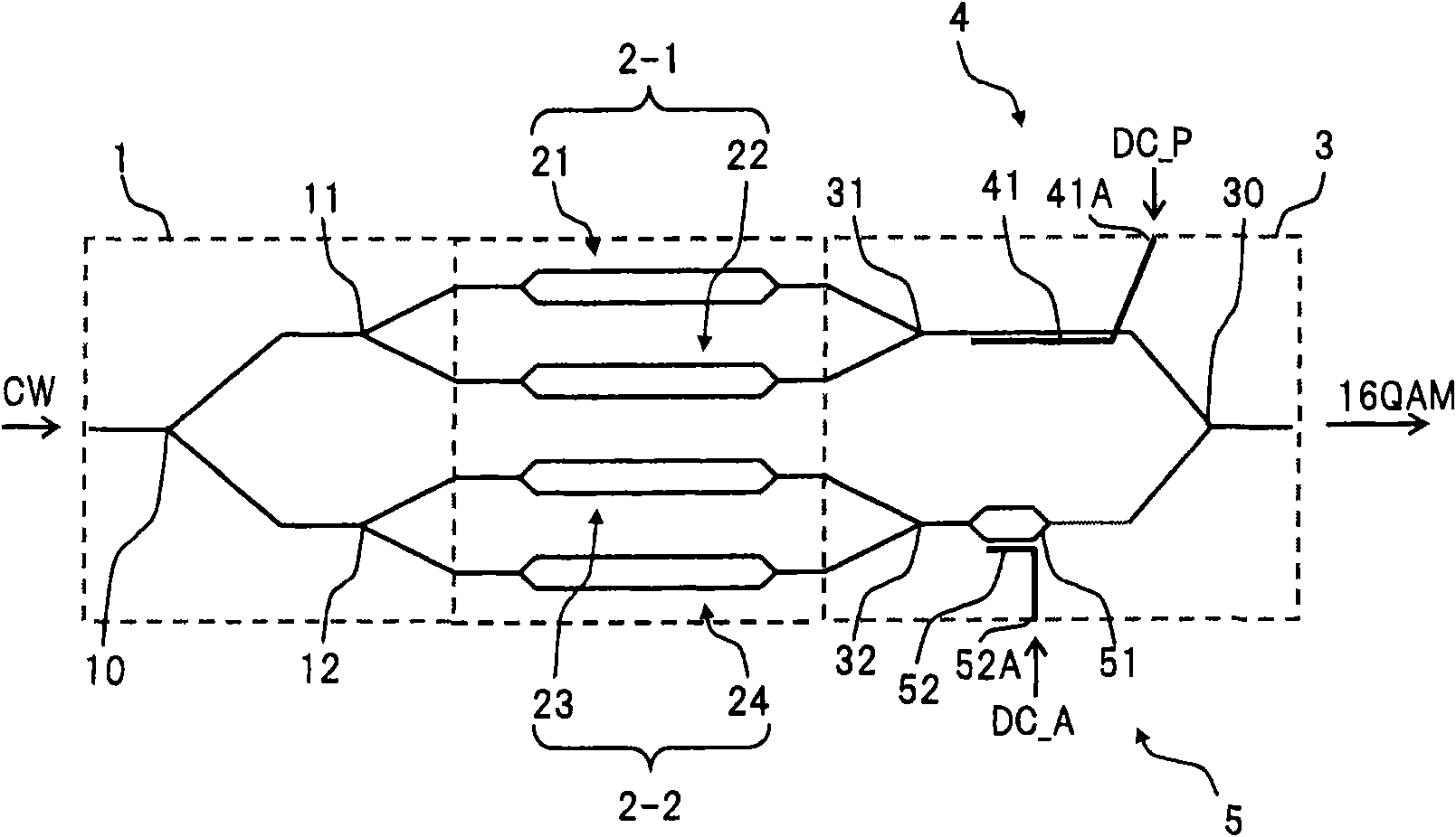
[0043] figure 1 The main structure of the light modulator in one embodiment of the present invention is shown.

[0044] exist figure 1 Among them, the optical modulator of this embodiment includes: an optical branching unit 1, which divides continuous light (CW) or optical pulse train provided externally into four beams of light; first to fourth phase modulation units 21, 22, 23, and 24, which are respectively connected to each output port of the optical branching part 1; the light combining part 3, which combines the light output from each phase modulating part 21 to 24 into two groups to generate the first combined light and the second combined light Two composite lights, and each composite light is combined into one to generate 16QAM signal light; an ...


PUM


Abstract

The optical modulator branches an input light into (2xN) lights in an optical branching section, and then phase modulates each of the branched lights in (2xN) phase modulating sections, and couples the phase modulated lights in an optical coupling section and generates a quadrature amplitude modulated (QAM) signal light having a 4 value. At this time, a relative difference of optical phases of the phase modulated lights is variably adjusted by an optical phase adjusting section. Moreover, a power ratio of the phase modulated lights is variably adjusted with an optical power adjusting section. As a result, it is possible to output 4 QAM signal light, with good signal quality.

Description

technical field [0001] The present invention relates to modulation technology in the field of optical communication, and in particular to an optical modulator for modulating light by using a quadrature amplitude modulation (QAM: Quadrature Amplitude Modulation) method, a control method and a control device for the optical modulator, and an optical modulator. Transmitters and optical transmission systems. Background technique [0002] This application is based on and claims priority from Japanese Patent Application No. 2008-092463 filed on March 31, 2008, the entire contents of which are incorporated herein by reference. [0003] Recently, for the purpose of wavelength multiplexing transmission of high-speed signal light of 40 gigabits per second (Gbps) and 100 Gbps at high density, research has been actively conducted on an optical modulation system with high spectral density. In addition, since the coherent reception technology has been actively researched and progressed, ...

Claims


Application Information

Patent Timeline
IPC IPC(8): H04B10/02H04B10/20G02F1/035H04B10/07H04B10/516H04B10/61
CPCH04B10/541H04B10/5053G02F1/0123G02F1/2255H04B10/50575
Inventor 星田刚司秋山祐一
Owner FUJITSU LTD
Why Eureka
Try Eureka