Cell cover locking structure

A battery cover and lock technology, which is applied to the structure of telephone sets, structural parts, battery pack parts, etc., can solve the problems of damage to portable electronic devices, laborious and inconvenient disassembly, and damage to battery covers, etc.

Inactive Publication Date: 2009-10-14
南通恒信精工机械有限公司
View PDF0 Cites 11 Cited by
  • Summary
  • Abstract
  • Description
  • Claims
  • Application Information

AI Technical Summary

Problems solved by technology

[0004] This type of battery cover is tightly and firmly combined with the body after installation, but it is laborious and inconvenient to disassemble and assemble, and excessive force will damage the battery cover, and even fall to the ground together with the portable electronic device, causing damage to the portable electronic device

Method used


Image

  • Cell cover locking structure
  • Cell cover locking structure
  • Cell cover locking structure

Examples


Embodiment Construction

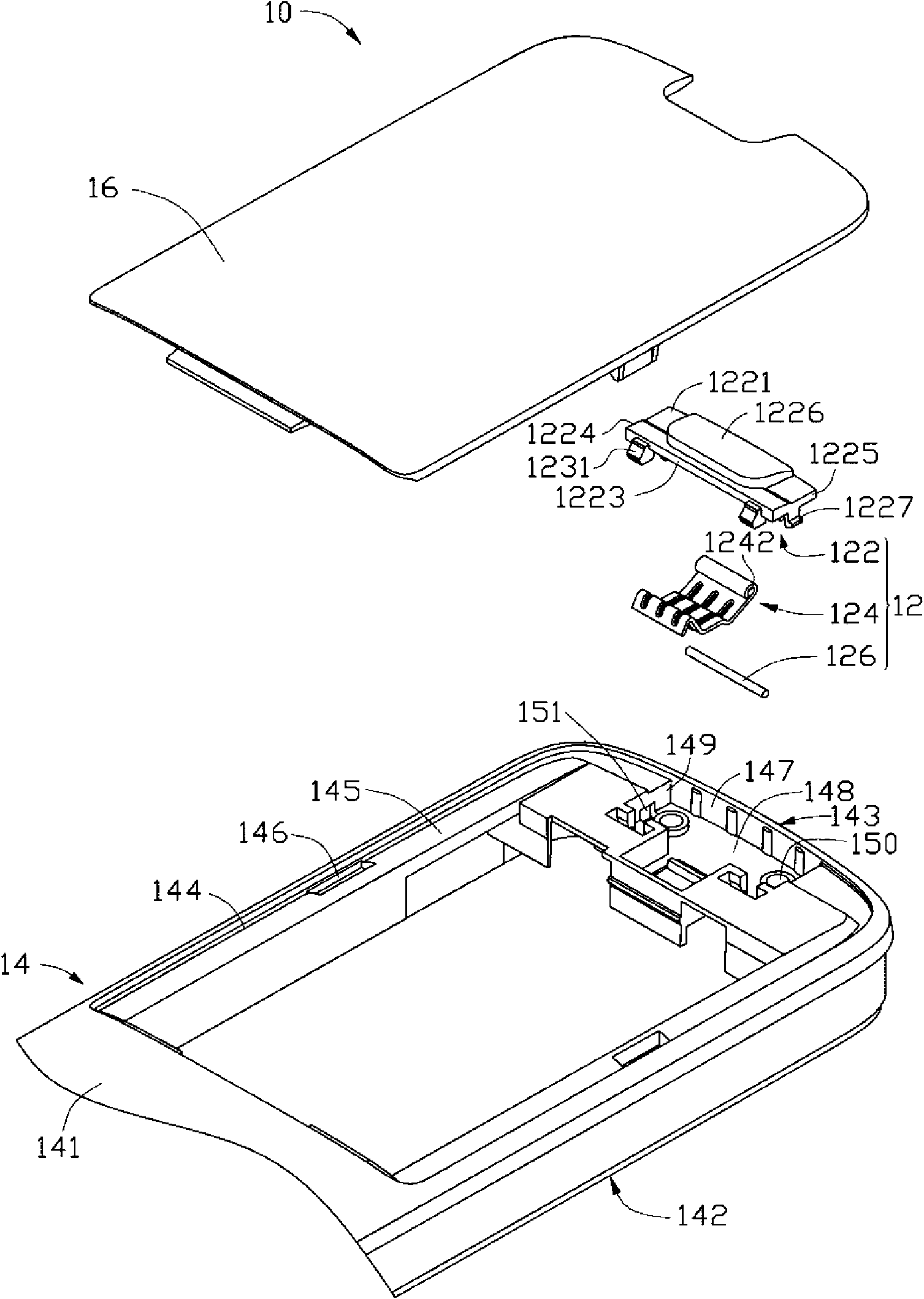
[0013] The invention discloses a locking structure of a battery cover, which is suitable for portable electronic devices such as mobile phones. In this embodiment, a mobile phone is taken as an example for illustration.

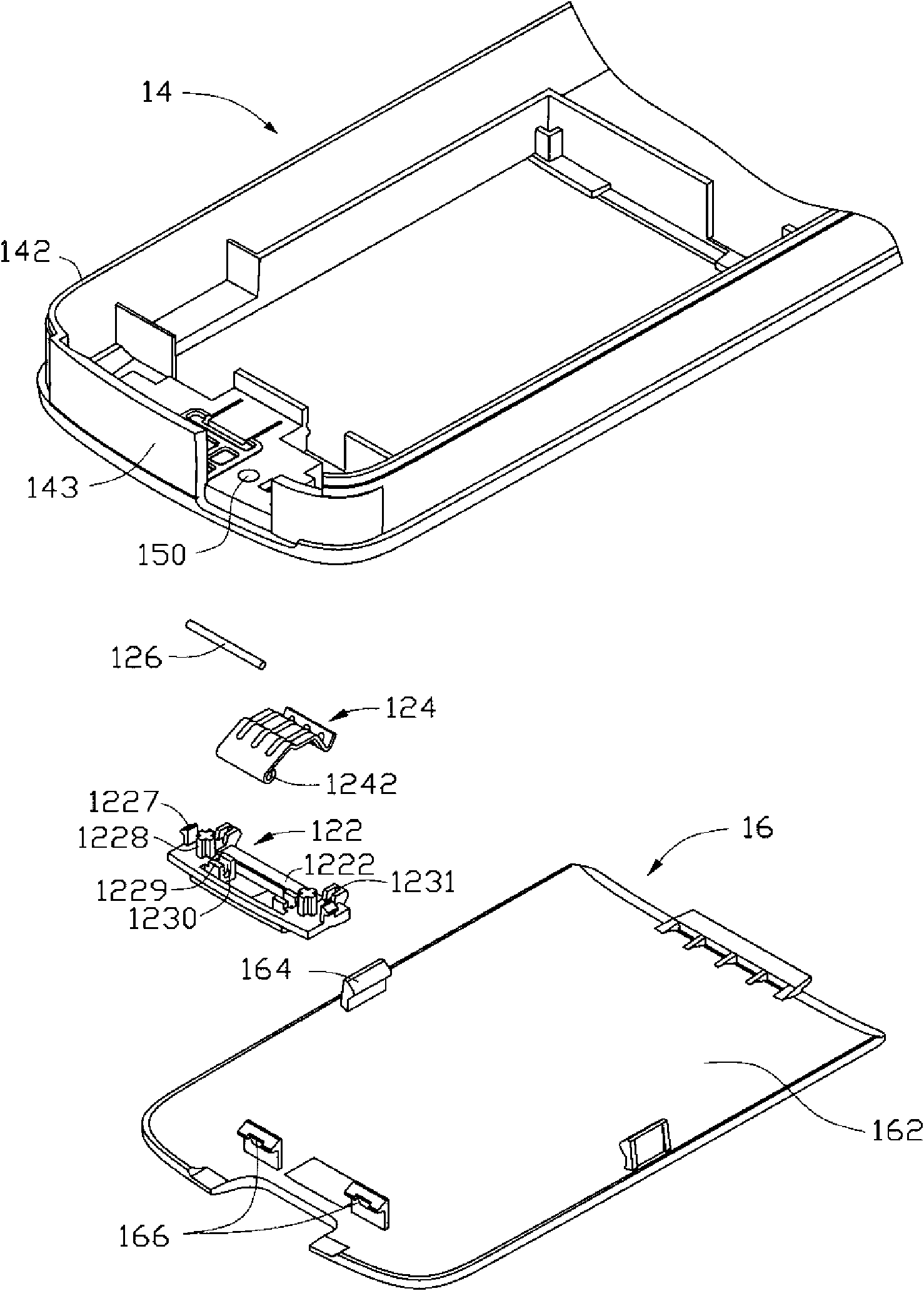
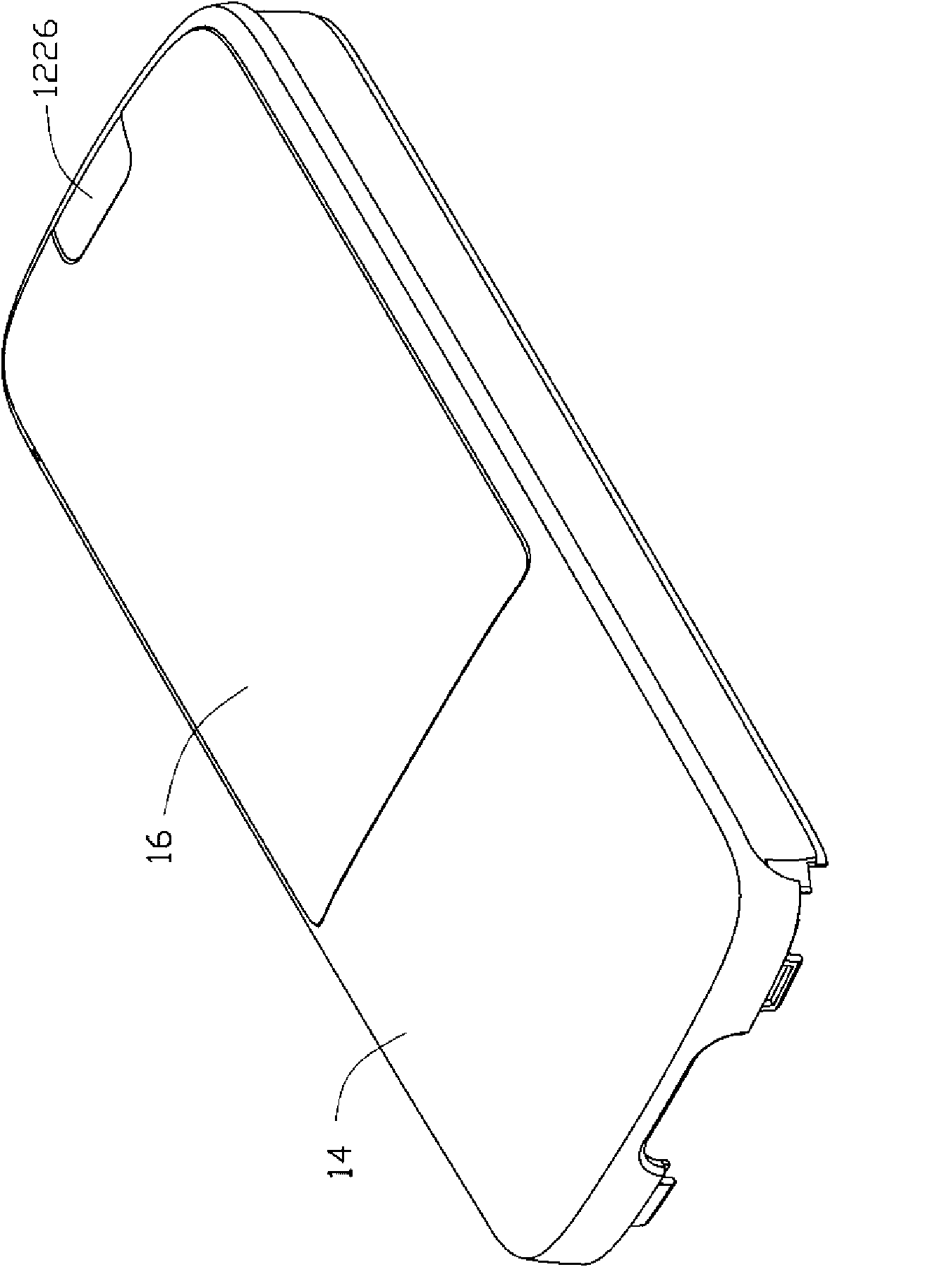
[0014] see Figure 1 to Figure 3 , The battery cover locking structure 10 of the present invention includes a button 12 , a body 14 and a battery cover 16 .

[0015] The button 12 includes a main body 122 , an elastic body 124 and a connecting shaft 126 .

[0016] The main body 122 is substantially a square plate, and includes a pressing surface 1221 , a joint surface 1222 , a side wall 1223 , a first end 1224 and a second end 1225 opposite to the first end 1224 . The pressing surface 1221 is opposite to the engaging surface 1222 . The pressing surface 1221 is an operation surface of the button 12 , and a pressing portion 1226 is disposed in the middle thereof. The joint surface 1222 is a joint surface of the button 12 and the body 14 .

[0017] The main ...


PUM


Abstract

The invention provides a cell cover locking structure, comprising a body and a cell cover, the body is internally provided with a cell cover slot in which the cell cover is held, the body is provided with a button slot on the bottom wall of the cell cover slot; the locking structure further comprises a button which is glidingly held in the button slot, the button comprises a main body on which a plurality of stop catch portions and an elastomer are arranged, the cell cover is provided with a plurality of lock-closing portions on the surface thereof facing toward the body, the stop catch portions are locked with the lock-closing portions so that the cell cover is locked on the body, one end of the elastomer is arranged on the main body, and when the button is pressed, the elastomer abuts against the cell cover in a direction away from the body.

Description

technical field [0001] The invention relates to a locking structure of a battery cover, in particular to a locking structure of a battery cover applied to portable electronic devices such as mobile phones. Background technique [0002] Mobile phones and personal digital assistants (Personal Digital Assistant, PDA) and other portable electronic devices are increasingly widely used, and the batteries that provide energy for portable electronic devices have to be replaced due to energy consumption. In order to make the battery easy to install, people have designed Many battery cover snap-lock structures. [0003] The locking structure of the battery cover of the existing portable electronic device is mostly fixed on the body by a hook and a buckle structure, that is, a pair of hooks are set at one end of the battery cover, and a locking pin is set at the other end, correspondingly at one end of the body. A pair of card slots are set, and a lock hole is set at the other end. W...

Claims


Application Information

Patent Timeline
Patent Type & Authority Applications(China)
IPC IPC(8): H01M2/10H05K5/03H05K7/00H04M1/02G06F1/16H01M50/247H01M50/262
CPCY02E60/12H04M1/0262H01M2/1066Y02E60/10
Inventor 黄国钊曾武春施政
Owner 南通恒信精工机械有限公司
Why Eureka
Try Eureka