Zoom lens and image pickup apparatus with same
An image pickup device, zoom lens technology, applied in the field of zoom lens, can solve the problems of difficult lens unit structure, shadow brightness, drop, etc.
- Summary
- Abstract
- Description
- Claims
- Application Information
AI Technical Summary
Problems solved by technology
Method used
Image

Examples
Embodiment approach
[0332] Hereinafter, embodiments of a zoom lens and an image pickup device according to the present invention will be described in detail with reference to the accompanying drawings. However, it should be understood that the present invention is not limited to these embodiments.
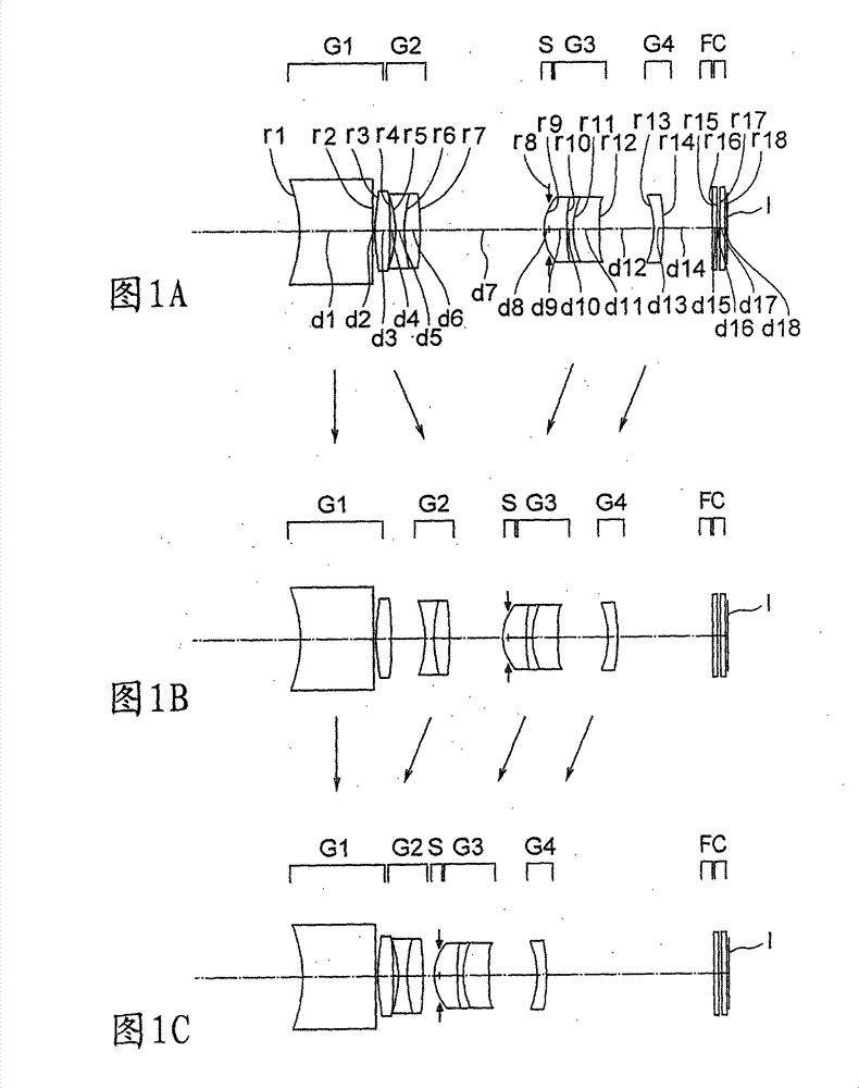
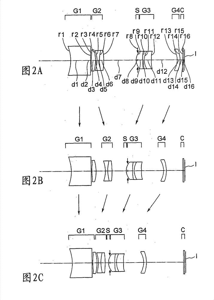
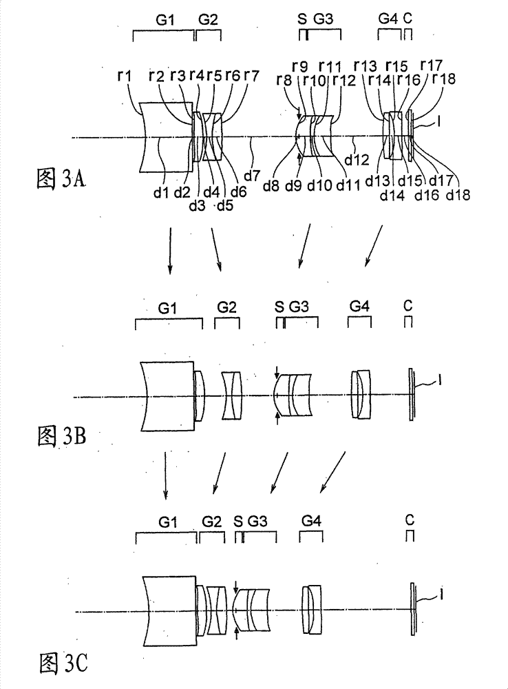
[0333] In the following, first to seventeenth embodiments of the zoom lens according to the present invention will be described. Figure 1A , 1B and 1C to 17A, 17B, and 17C are zoom lenses according to the first to seventeenth embodiments of the present invention at the wide-angle end ( Figures 1A to 17A ), at intermediate focal lengths ( Figures 1B to 17B ) and at the telephoto end ( Figures 1C to 17C ) profile. exist Figure 1A to Figure 17C Among them, the first lens unit is denoted by G1, the second lens unit is denoted by G2, the aperture stop is denoted by S, the third lens unit is denoted by G3, and the fourth lens unit is denoted by G4. The wavelength range of light restricts the coati...
example 1
[0404] unit mm
[0405] surface data
[0406] Surface number r d nd vd
[0407]1* -9.669 7.20 1.88300 40.76
[0408] 2 ∞ 0.20
[0409] 3* 12.688 1.50 1.80610 40.92
[0410] 4* -462.757 variable
[0411] 5 -10.258 0.80 1.88300 40.76
[0412] 6 14.005 1.54 1.82114 24.06
[0413] 7* -34.185 variable
[0414] 8(S) ∞ -0.50
[0415] 9* 4.980 2.30 1.58313 59.38
[0416] 10 22.870 0.58 1.84666 23.78
[0417] 11 7.514 2.50 1.59201 67.02
[0418] 12* -75.687 variable
[0419] 13* -9.866 1.00 1.52542 55.78
[0420] 14 -18.904 variable
[0421] 15 ∞ 0.50 1.53996 59.45
[0422] 16 ∞ 0.27
[0423] 17 ∞ 0.50 1.51633 64.14
[0424] 18 ∞ 0.23
[0425] Image plane (light receiving surface)
[0426] Aspheric Data
[0427] first surface
[0428] K=-6.995, A4=8.86364e-05, A6=-1.36794e-06, A8=9.48088e-08, A10=-1.27868e-09
[0429] third surface
[0430] K=0.000, A4=-8.08906e-04, A6=4.52266e-07, A8=-1.05791e-06
[0431] fourth surface
[0432] K=13073.884, A4=-1.96823e-04, A6...
example 2
[0460] unit mm
[0461] surface data
[0462] Surface number r d nd vd
[0463] 1* -10.060 7.20 1.88300 40.76
[0464] 2 ∞ 0.20
[0465] 3* 21.209 1.50 1.80610 40.92
[0466] 4* -31.550 variable
[0467] 5 -11.016 0.80 1.88300 40.76
[0468] 6 13.255 1.54 1.82114 24.06
[0469] 7* -39.143 variable
[0470] 8(S) ∞ -0.50
[0471] 9* 4.970 2.30 1.58313 59.38
[0472] 10 22.888 0.58 1.84666 23.78
[0473] 11 7.309 2.50 1.59201 67.02
[0474] 12* -200.331 variable
[0475] 13* -7.210 1.00 1.49700 81.54
[0476] 14 -11.462 variable
[0477] 15 ∞ 0.40 1.51633 64.14
[0478] 16 ∞ 0.35
[0479] Image plane (light receiving surface)
[0480] Aspheric Data
[0481] first surface
[0482] K=-5.778, A4=1.53140e-04, A6=-1.85187e-06, A8=8.77509e-08, A10=-1.31368e-09
[0483] third surface
[0484] K=0.000, A4=-1.04142e-03, A6=-2.26093e-05, A8=-1.10204e-06
[0485] fourth surface
[0486] K=0.000, A4=-5.76267e-04, A6=-2.99028e-05, A8=-4.64492e-07, A10=9.30735e-09
[048...
PUM
 Abstract
Description
Claims
Application Information
 - R&D
- Intellectual Property
- Life Sciences
- Materials
- Tech Scout
- Unparalleled Data Quality
- Higher Quality Content
- 60% Fewer Hallucinations
Browse by: Latest US Patents, China's latest patents, Technical Efficacy Thesaurus, Application Domain, Technology Topic, Popular Technical Reports.
© 2025 PatSnap. All rights reserved.Legal|Privacy policy|Modern Slavery Act Transparency Statement|Sitemap|About US| Contact US: help@patsnap.com