Multiple-sprue fluid conveying appliance

A fluid conveying, multi-channel technology, which is applied to the components of pumping devices for elastic fluids, liquid variable-capacity machines, liquid fuel engines, etc., and can solve problems such as increasing the complexity of the pump system.

Active Publication Date: 2009-10-28
MICROJET TECH
View PDF0 Cites 3 Cited by
  • Summary
  • Abstract
  • Description
  • Claims
  • Application Information

AI Technical Summary

Problems solved by technology

[0007] The main purpose of the present invention is to provide a multi-channel fluid delivery device to solve the problem of mixing two different liquids in different proportions with the existing micropump structure, It needs to be drawn by two pumps according to different proportions and then stirred and mixed, or only one pump must be used, but it must be equipped with an external flow regulating valve, which will increase the complexity of the entire pump system and other disadvantages

Method used


Image

  • Multiple-sprue fluid conveying appliance
  • Multiple-sprue fluid conveying appliance
  • Multiple-sprue fluid conveying appliance

Examples


Embodiment Construction

[0024] Some typical embodiments embodying the features and advantages of the present invention will be described in detail in the description in the following paragraphs. It should be understood that the invention is capable of various changes in different aspects without departing from the scope of the invention, and that the description and illustrations therein are illustrative in nature and not limiting. this invention.

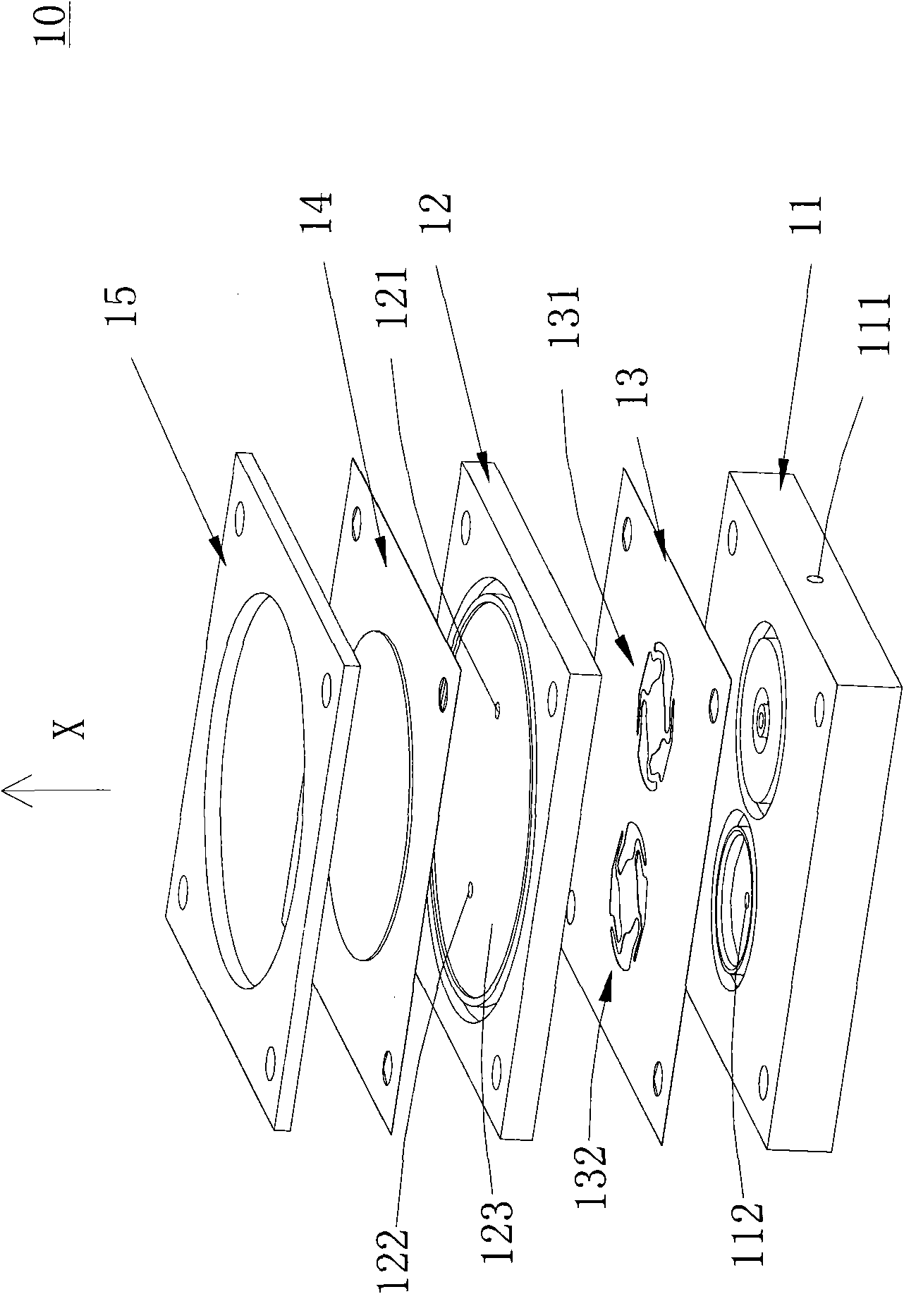
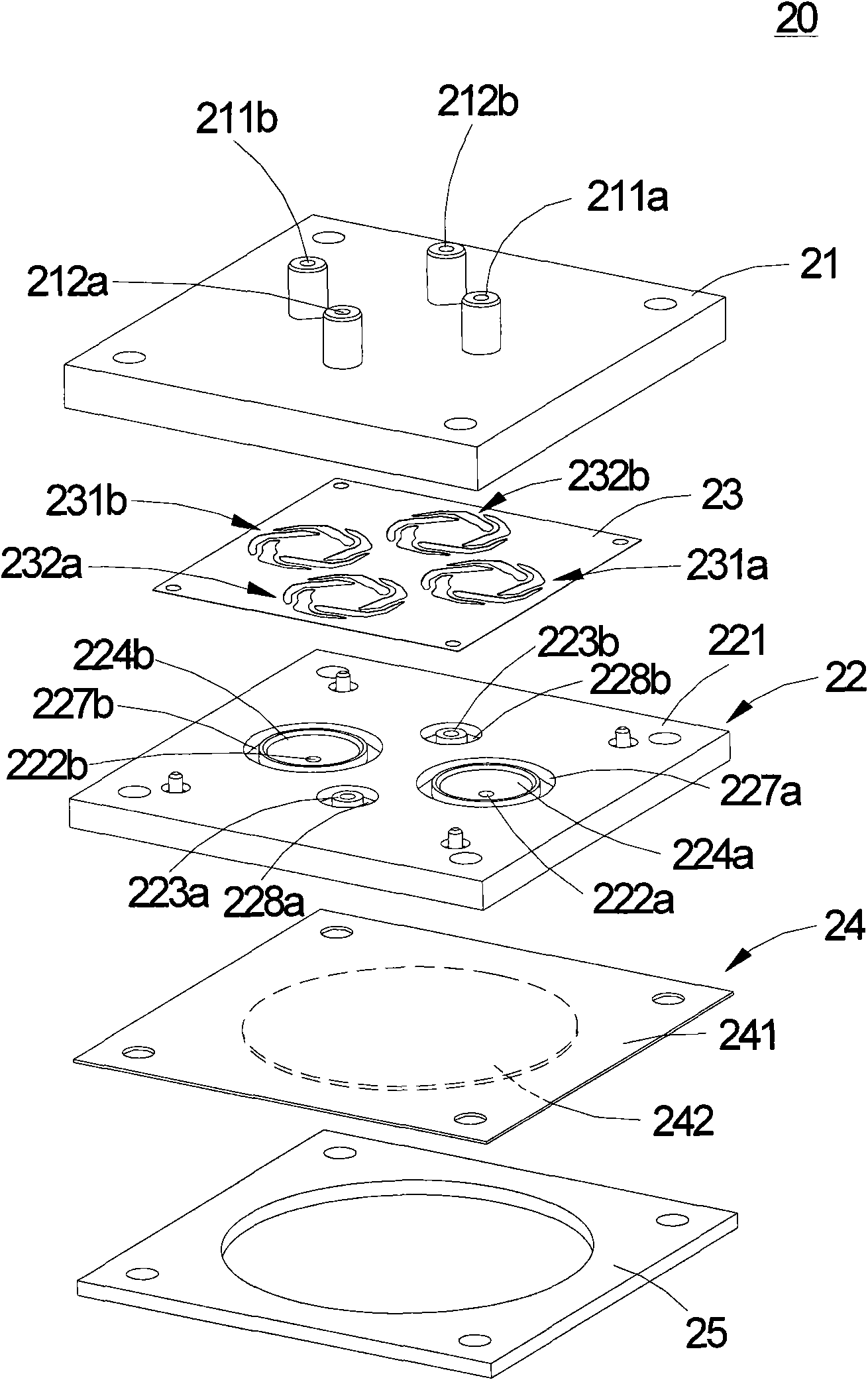
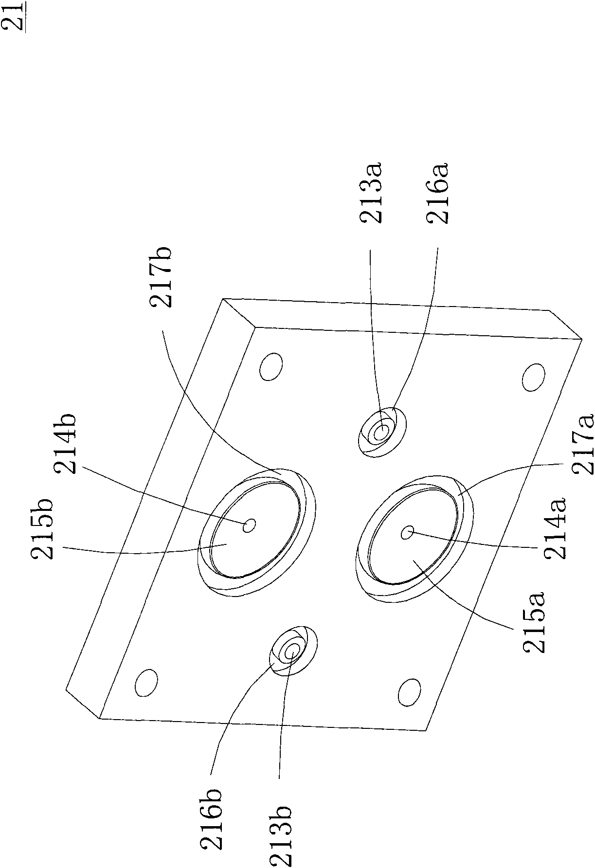
[0025] The multi-channel fluid delivery device of the present invention is mainly based on the configuration concept of a single pressure chamber and an actuator in conjunction with multiple flow pipes, multiple inlets and outlets, and multiple valve structures, so that the flow rate can be increased without increasing the overall size. And the head is greatly increased, which is very suitable for applications with relatively high flow and head requirements.

[0026] Please refer to Fig. 2 (a), which is a schematic diagram of an exploded structure of a m...


PUM


Abstract

The invention relates to a multiple-sprue fluid conveying appliance used for conveying fluid, which comprises a valve body seat provided with at least one outlet passage and at least one inlet passage, a valve body cover combined with the valve body seat mutually in a stacking way, a valve body membrane arranged between the valve body seat and the valve body cover and provided with over two valve structures having same thickness and made of same material, a plurality of temporary storage rooms arranged between the valve body membrane and the valve body cover and between the valve body membrane and the valve body seat, and a rapping device, wherein the periphery of the rapping device is fixedly arranged at the valve body cover.

Description

technical field [0001] The invention relates to a fluid delivery device, in particular to a multi-channel fluid delivery device suitable for a micropump structure. Background technique [0002] At present, in various fields, whether it is medicine, computer technology, printing, energy and other industries, products are developing towards refinement and miniaturization. Among them, the fluid delivery structures included in products such as micropumps, sprayers, inkjet heads, and industrial printing devices As its key technology, how to break through its technical bottleneck with the help of innovative structure is an important content of development. [0003] see figure 1 , which is a structural schematic diagram of an existing micropump structure. The existing micropump structure 10 is composed of a valve body seat 11, a valve body cover 12, a valve body film 13, a microactuator 14 and a cover body 15, wherein, The valve body film 13 includes an inlet valve structure 131 ...

Claims


Application Information

Patent Timeline
Patent Type & Authority Applications(China)
IPC IPC(8): F04B43/04F04B53/10
Inventor 陈世昌张英伦余荣侯邱士哲
Owner MICROJET TECH
Why Eureka
Try Eureka