
Low-speed microwave detection system

A microwave detection, low-speed technology, applied in radio wave measurement systems, measurement devices, reflection/re-radiation of radio waves, etc. Signal coupling, the effect of ensuring radiation characteristics

Active Publication Date: 2011-04-27
SHANGHAI KOHLER ELECTRONICS TECH
View PDF0 Cites 0 Cited by
  • Summary
  • Abstract
  • Description
  • Claims
  • Application Information

AI Technical Summary

Problems solved by technology

For the transceiver antenna, in the prior art, it is usually a dual-antenna system and a single-antenna transceiver system in which the transceiver antenna is separated. For the front-end RF receiving circuit in the single-antenna transceiver system, the circulator is generally used to isolate the transceiver signal, but it cannot realize the front-end system. Miniaturization and low cost requirements

Method used


Image

  • Low-speed microwave detection system
  • Low-speed microwave detection system

Examples


Embodiment approach

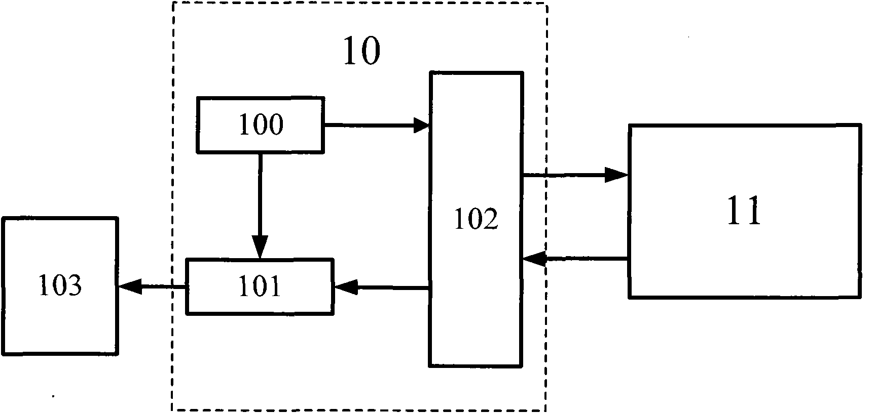
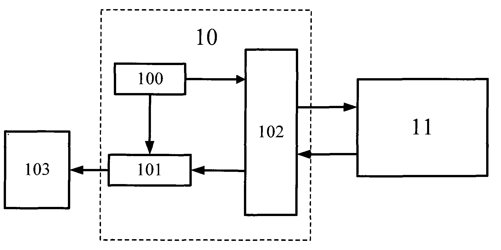
[0017] see figure 1 Shown is a block diagram of the composition of the low-speed microwave detection system for kitchen and bathroom installations of the present invention. The low-speed microwave detection system for kitchen and bathroom installations of the present invention includes a front-end radio frequency circuit 10 and a transceiver antenna 11. Wherein the transmitting and receiving antenna 11 is a single-antenna system shared by transmitting signals and receiving echo signals. The front-end radio frequency circuit 10 includes an oscillator 100 and a mixer 101 . The oscillator 100 transmits one eigensignal to the mixer 101 , wherein the front-end radio frequency circuit 10 further includes a power divider 102 . The power divider 102 receives another eigensignal of the oscillator 100 and transmits it to the transceiver antenna 11 . The transceiver antenna 11 transmits the received signal, and the power divider 102 also receives the echo signal received by the transce...


PUM


Abstract

The invention relates to a low-speed microwave detection system used on a kitchen and sanitary bath equipment, which comprises a front-end radio frequency circuit and a transmitting and receiving antenna, wherein the front-end radio frequency circuit comprises an oscillator and a frequency mixer; the oscillator transmits one path of intrinsic signals to the frequency mixer; the front-end radio frequency circuit also comprises a power divider which receives the other path of intrinsic signals of the oscillator and transmits the other path of the intrinsic signals to the transmitting and receiving antenna; the antenna transmits the received signals to the outside; and the power divider also receives echo signals of the transmitting and receiving antenna, outputs the echo signals to the frequency mixer for frequency mixing with the intrinsic signals, and outputs differential signals. Therefore, due to the design of the power divider in the front-end radio frequency circuit, most power outputted by the oscillator is coupled to a port of the transmitting and receiving antenna and partial power is coupled to an intrinsic port of the frequency mixer, so that the power divider not only canreplace an annular isolator and meet the requirements of miniaturation and low cost of the front-end radio frequency circuit but also can guarantee that reflected echo signals are isolated from output signals of the oscillator.

Description

【Technical field】 [0001] The invention relates to a low-speed microwave detection system, in particular to a detection system using a microwave Doppler sensor system used in kitchen and sanitary facilities. 【Background technique】 [0002] The microwave Doppler sensor uses the principle of Doppler radar to transmit a low-power microwave and receive the energy reflected by the moving target. Once a moving target is detected by it, the electromagnetic wave signal returned by the target is received by the detection sensor and mixed with the local oscillator signal, and the sensor outputs a low frequency voltage as a result. Its operating frequency is 10.525GHz, which can detect low-speed moving targets without being affected by heat, noise, humidity, airflow, dust, etc. It is suitable for use in harsh environments, and has the characteristics of anti-interference, high sensitivity, extremely stable performance and high cost performance. [0003] In practice, the microwave Doppl...

Claims


Application Information

Patent Timeline
Patent Type & Authority Patents(China)
IPC IPC(8): G01S13/02G01S13/04
Inventor 陈忠民高鹏程
Owner SHANGHAI KOHLER ELECTRONICS TECH
Learn More