Signal acceptance method, signal transmitting method, signal acceptance and transmitting device

A signal receiving and signal technology, applied in the field of communication, can solve the problems of increased mutual coupling strength between array elements, reduced influence between array elements, large size of smart antenna array, etc., to achieve the effect of ensuring radiation characteristics and reducing area

Inactive Publication Date: 2012-09-05
ZTE CORP
View PDF0 Cites 0 Cited by
  • Summary
  • Abstract
  • Description
  • Claims
  • Application Information

AI Technical Summary

Problems solved by technology

However, due to the requirement of the distance between the array elements, the size of the smart antenna array will be large, which will have an adverse effect on the actual application.
[0006] On the other hand, if the element spacing of the antenna array is reduced, the mutual coupling strength between the elements will increase, which will affect the directivity of the array and reduce the shaping efficiency of the antenna array.
[0007] However, there is no technical solution that can reduce the mutual coupling strength between array elements, reduce the influence between array elements, and at the same time make the shaping efficiency of smart antennas meet the requirements

Method used


Image

  • Signal acceptance method, signal transmitting method, signal acceptance and transmitting device
  • Signal acceptance method, signal transmitting method, signal acceptance and transmitting device
  • Signal acceptance method, signal transmitting method, signal acceptance and transmitting device

Examples


Embodiment 1

[0029] In this embodiment, a signal receiving method is provided, which is used for an array antenna whose inter-element spacing is smaller than the normal inter-element spacing.

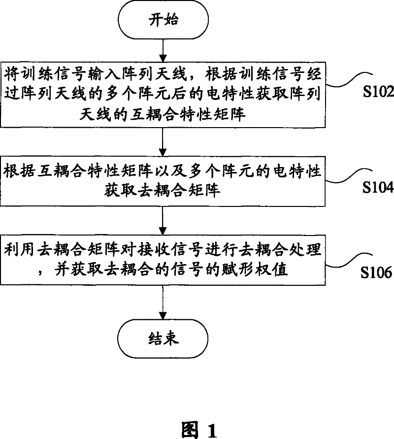
[0030] Such as figure 1 As shown, the signal receiving method according to this embodiment includes: step S102, inputting the training signal into the array antenna, and obtaining the mutual coupling characteristic matrix of the array antenna according to the electrical characteristics of the training signal after passing through a plurality of array elements of the array antenna; step S104, Obtain a decoupling matrix according to the mutual coupling characteristic matrix and the electrical characteristics of multiple array elements; and step S106 , decoupling the received signal by using the decoupling matrix, and obtaining the weighted value of the decoupled signal.

[0031] Wherein, the distance between the multiple array elements is less than 1 / 3λ and greater than 0, and generally the distance b...

Embodiment 2

[0045] In this embodiment, a signal transmitting method is provided, which is used for an array antenna whose inter-element spacing is smaller than the normal inter-element spacing.

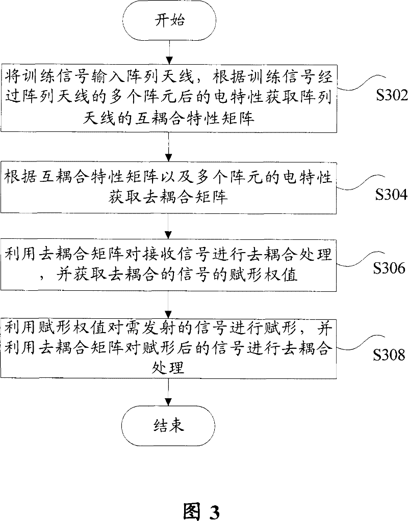
[0046] Such as image 3 The shown signal transmission method according to this embodiment includes: step S302, inputting the training signal into the array antenna, and obtaining the mutual coupling characteristic matrix of the array antenna according to the electrical characteristics of the training signal after passing through a plurality of array elements of the array antenna; step S304, according to Obtain a decoupling matrix from the mutual coupling characteristic matrix and the electrical characteristics of multiple array elements; step S306, use the decoupling matrix to perform decoupling processing on the received signal, and obtain the weighted value of the decoupled signal; and step S308, use the assigned The shape weight shapes the signal to be transmitted, and uses the decoupling matr...


PUM


Abstract

The invention discloses a signal receiving method for array antenna with array element space less than normal array element space; the method includes that training signals are inputted into an array antenna; the inter-coupling characteristic matrix of the array antenna is obtained according to the electrical characteristics of the training signals which are transmitted in a plurality of array elements of the array antenna; a coupling matrix is obtained according to the inter-coupling characteristic matrix and the electrical characteristics of array elements; and a decoupling matrix is adopted to perform decoupling processing towards the received signals, and obtain shaping weight of the decoupling signal. Besides, the invention also discloses a signal transmission method, a signal receiver and transmitter device. When the invention is in use, the area of an intelligent antenna is reduced, and the radiation characteristic of intelligent antenna is maintained at the same time.

Description

technical field [0001] The present invention relates to the communication field, and in particular, relates to a signal receiving method, a signal transmitting method, and a signal receiving and transmitting device for an array antenna whose inter-array spacing is smaller than the normal inter-array spacing. Background technique [0002] With the development of space-time signal processing technology, multi-antenna systems have been widely used in the field of wireless communication. [0003] The smart antenna technology is one of the multi-antenna system technologies, which mainly utilizes the array gain generated by the in-phase superposition effect of signals generated at the receiving end or the transmitting end of the multi-antenna system, thereby improving system performance. [0004] In the actual antenna array, due to the interaction between the array elements, the current amplitude and phase distribution on each array element will be greatly changed compared with th...

Claims


Application Information

Patent Timeline
Patent Type & Authority Patents(China)
IPC IPC(8): H04B7/06H04B7/08
Inventor 曾召华史凡
Owner ZTE CORP
Why Eureka
Try Eureka