Actuator for optical scanning

A technology for actuators and optical scanning, applied in optics, instruments, optical components, etc., can solve problems such as poor flexibility, inability to adjust the movable range, and inability to adjust the movable range of movable parts, etc., to achieve the effect of flexible adjustment

Inactive Publication Date: 2009-11-11
NHK SPRING CO LTD
View PDF1 Cites 2 Cited by
  • Summary
  • Abstract
  • Description
  • Claims
  • Application Information

AI Technical Summary

Problems solved by technology

Therefore, the existing actuators for optical scanning have the following problems: the movable range of the movable part cannot be adjusted, especially the movable range of the movable part along the length direction of the leaf spring cannot be adjusted, and the flexibility is not good.

Method used


Image

  • Actuator for optical scanning
  • Actuator for optical scanning
  • Actuator for optical scanning

Examples


Embodiment approach 1

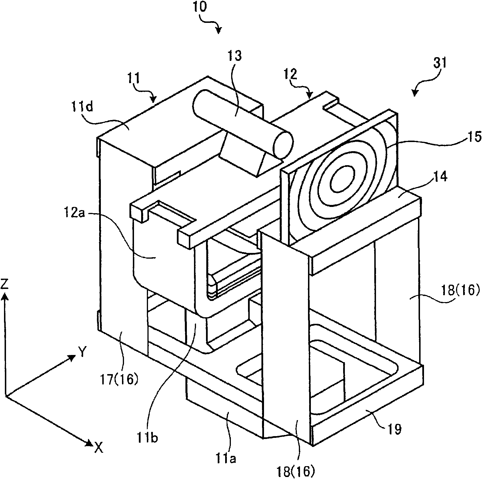
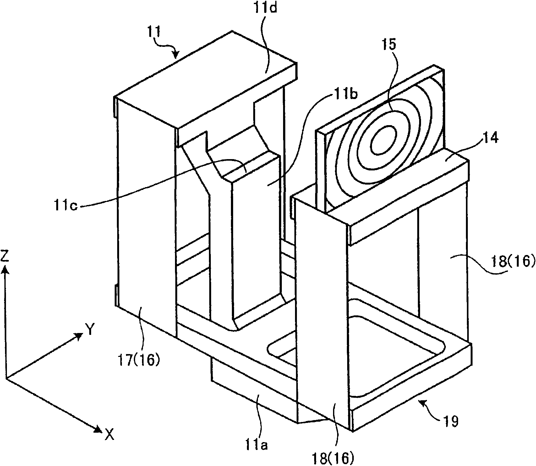
[0050] Next, Embodiment 1 according to the optical scanning actuator of the present invention will be described in detail with reference to the drawings. figure 1 It is a perspective view showing the optical scanning actuator according to the first embodiment. figure 2It is a perspective view of the optical scanning actuator with the drive unit removed.

[0051] Such as figure 1 As shown, the optical scanning actuator 10 includes a main body 11 , a movable member 14 , a connecting member 16 , and a deformation relaxing member 19 .

[0052] Such as figure 1 and figure 2 As shown, the main body 11 is erected on the base 11a with a pillar 11b, and a workbench 11d is formed on the upper part of the pillar 11b through a stepped setting part 11c, and a fixing member of the driving part 12 is set on the setting part 11c. The driving unit 12 is provided with a scanning light source 13 on the upper surface, and like the driving unit 6 of the conventional optical scanning actua...

Embodiment approach 2

[0073] Next, Embodiment 2 of the optical scanning actuator of the present invention will be described in detail with reference to the drawings. In contrast to the optical scanning actuator according to Embodiment 1, which has fixed side leaf springs and movable side leaf springs arranged front and rear, the optical scanning actuator according to Embodiment 2 has fixed side leaf springs and movable side leaf springs arranged side to side. Figure 11 It is a perspective view showing the actuator for optical scanning according to the second embodiment. Figure 12 It is a schematic diagram schematically showing the positional relationship of the fixed member, the movable member, the deformation relieving member, the fixed-side leaf spring, and the movable-side leaf spring when the movable member swings to the right.

[0074] Such as Figure 11 As shown, the optical scanning actuator 30 includes a main body 31 , a movable member 34 , a connecting member 36 , and a deformation rela...

Embodiment approach 3

[0090] Next, Embodiment 3 of the optical scanning actuator of the present invention will be described in detail with reference to the drawings. In the optical scanning actuator of Embodiment 1, the fixed-side leaf spring and the movable-side leaf spring are arranged in a direction perpendicular to the optical axis of light emitted from the scanning light source, whereas the optical scanning actuator of Embodiment 3 The device arranges the fixed-side leaf spring and the movable-side leaf spring in the direction of the optical axis of light emitted from the scanning light source. Figure 14 It is a perspective view showing an optical scanning actuator according to Embodiment 3. FIG. Here, components of the optical scanning actuator according to the third embodiment and the optical scanning actuator according to the first embodiment are assigned the same reference numerals.

[0091] The actuator 40 for optical scanning is provided with a driving part 12 on the main body 11, and ...


PUM


Abstract

An optical scanning actuator (10) includes a fixed member (11) having a light source (13), a movable member (14) having an optical element (15) that deflects light emitted from the light source and caused to vibrate by a driving unit (12) in a direction perpendicular to an optical axis of the optical element, and a joint unit (16) that connects the fixed member and the movable member, supports the movable member, and is bent in a direction perpendicular to an optical axis of light emitted from the light source by vibration of the movable member. The optical scanning actuator (10) scans light emitted from the light source in an vibration direction by vibration of the optical element along with the vibration of the movable member. The joint unit (16) includes pairs of joint members (17, 18) connected via at least one deformation reducing member (19) that reduces bending deformation of the joint members caused by the vibration of the movable member.

Description

technical field [0001] The present invention relates to an actuator for optical scanning. Background technique [0002] As conventional devices utilizing scanning devices such as laser light, scanning laser radar devices, laser scanners, laser printers, laser markers, object monitoring devices, and the like are known. Among these devices, for example, in a scanning device used in a scanning laser radar device for preventing vehicle collisions, a leaf spring type optical scanning actuator is known, and the leaf spring type optical scanning actuator is based on Optical components such as lenses are installed on the movable member at the front end of the leaf spring member whose end is fixed, and the movable member is swung by an electromagnetic drive mechanism, and the light emitted from the light source fixed at a fixed position is made use of the optical member. Scanning is performed by refraction (for example, refer to Patent Document 1). [0003] In this way, as a leaf s...

Claims


Application Information

Patent Timeline
Patent Type & Authority Applications(China)
IPC IPC(8): G02B26/10
CPCG01S7/4814G02B3/08G02B26/0875G02B26/10G02B26/103
Inventor 平田贵史重松良平饭野信次
Owner NHK SPRING CO LTD
Why Eureka
Try Eureka