Mechanical type three-dimensional compact spinning device

A mechanical and compact technology, applied in the direction of spinning machines, textiles and papermaking, drafting equipment, etc., can solve the problems of yarn blocking, high production cost, and yarn quality in the twisting triangle area cannot be eliminated

Inactive Publication Date: 2009-11-18
绍兴华裕纺机有限公司
View PDF2 Cites 15 Cited by
  • Summary
  • Abstract
  • Description
  • Claims
  • Application Information

AI Technical Summary

Problems solved by technology

For example, a compact spinning device with patent No. 03228410.1 is provided with an air suction pipe with two ends fixed on two adjacent roller seats with air suction port and exhaust port, which is set outside the air suction pipe and corresponds to the position of the air suction port. The cohesive sleeve with a condensation groove in the circumferential direction of the cohesive sleeve, the tension device stuck in the cohesive sleeve, the air-permeable conveying ring and the transmission pressure device set on the cohesive sleeve, the compact spinning device can make the fiber bundle output by the front roller Under the action of negative pressure generated by the exhaust system, it is adsorbed on the air-permeable conveying ring, and under the action of the pressurized transmission device and the air-permeable conveying ring, the fiber bundle is tightened and straightened to achieve twisting into yarn. The yarn device can better solve the original "hairiness" problem and improve the yarn quality, but there are also some shortcomings, such as complex structure and high production cost; and the compact spinning device and the roller are driven by different power devices. It is easy to cause the speed of the compact spinning device to be out of sync with the speed of the rollers, resulting in yarn blocking and yarn breakage, which cannot eliminate the twisting triangle and affect the quality of the yarn

Method used


Image

  • Mechanical type three-dimensional compact spinning device
  • Mechanical type three-dimensional compact spinning device
  • Mechanical type three-dimensional compact spinning device

Examples


Embodiment Construction

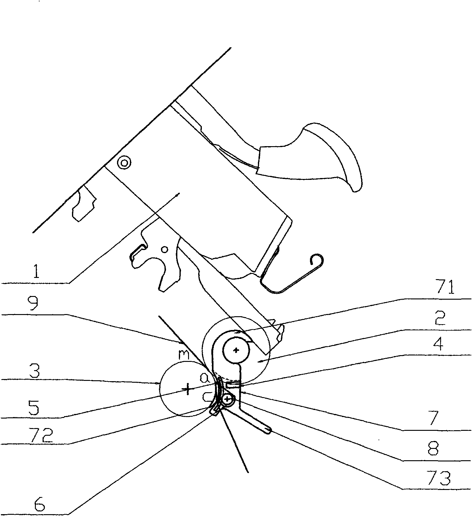
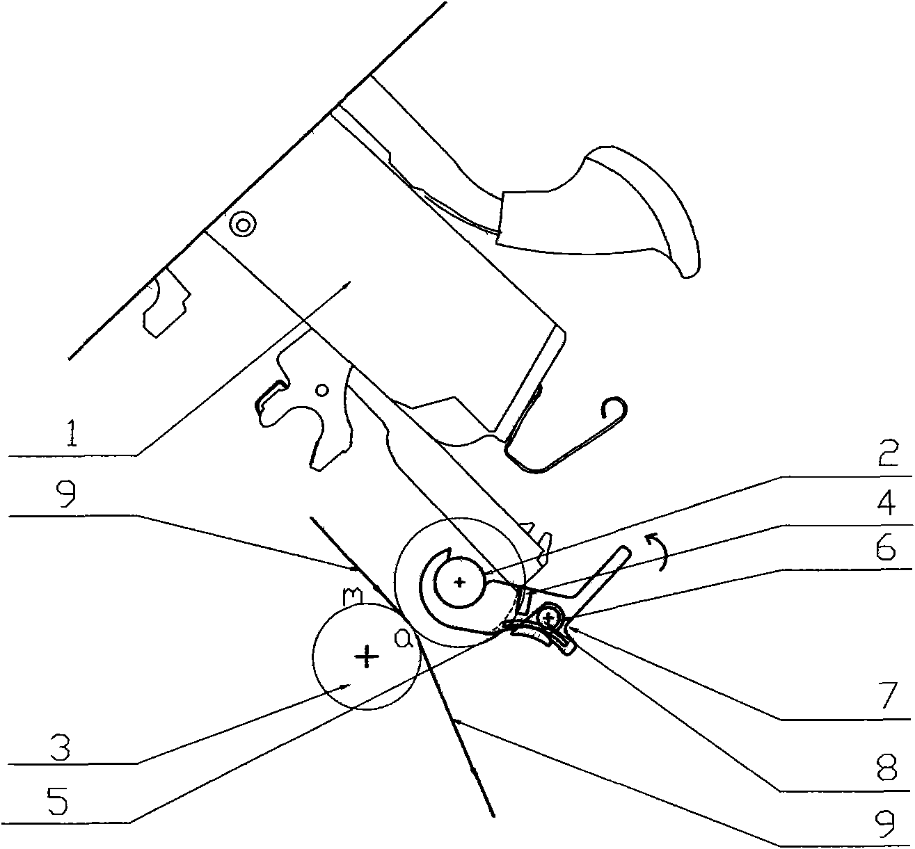
[0013] Such as figure 1 , figure 2 As shown, the bottom top roller 2 is installed on the cradle 1 of the spinning frame, and the bottom roller 3 is installed under the cradle 1 and pressed tightly on the bottom top roller 2. The gap formed between the bottom roller 3 and the bottom top roller 2 The contact area a forms the drafting area m between the pre-drafting device and the output end a of the drafting press roller composed of the bottom roller 3 and the bottom top roller 2 . Cage 7 has a movable end 71, arc recess 72 and handle 73, wherein, cage 7 is installed on the lower top roller 2 by movable end 71, and can rotate a certain angle around lower top roller 2, the arc of cage 7 The concave part 72 faces the side of the bottom roller 3, so as to fit the outer surface of the bottom roller 3. The handle 73 is used to operate the cage 7, so as to conveniently switch between the two working states of compact spinning and ordinary ring spinning. Two sets of magnets are inst...


PUM


Abstract

The invention discloses a mechanical type three-dimensional compact spinning device, belonging to the technical field of textile machinery. A reel of a spinning frame is provided with a lower leather roller, and a bottom roll is installed on the lower leather roller pressed under the reel. The device is characterized by further comprising a retaining frame which is provided with a movable end and a handle, and the retaining frame is installed on the lower leather roller by the movable end and is provided with two groups of magnet, wherein, the first magnet is installed at the position on the retaining frame corresponding to the lower leather roller, and the second magnet is installed at the position on the retaining frame corresponding to the bottom roll; a compact part is arranged on the retaining frame by a shaft, and one side of the compact part facing to the bottom roll is cambered and clings to the bottom roll; the cambered surface of the compact part is provided with a plurality of cluster grooves which face to the coming direction of yarn, has a funnel shape and is from wide to narrow. The invention has simple structure, good cluster effect and uniform yarn strips after twisting.

Description

technical field [0001] The invention relates to a textile machine, in particular to a mechanical three-dimensional compact spinning device. Background technique [0002] In the spinning process of the traditional spinning frame, after the drafted sliver leaves the front roller with a certain width and in a free state, it is immediately processed into a yarn, and a spun yarn is formed in the yarn forming area In the triangular area, because the loose fibers in the spinning triangular area cannot be well controlled, many fiber whiskers around the yarn sliver will be scattered in advance and cannot be bundled, and the scattered fibers will protrude out of the yarn because they cannot be squeezed into the yarn The "hairiness" that occurs in spinning is formed, which seriously affects the yarn quality and reduces the fiber utilization. Therefore, it is necessary to improve the conveying form of the sliver before twisting, even if the sliver is parallel, straight and closely arra...

Claims


Application Information

Patent Timeline
Patent Type & Authority Applications(China)
IPC IPC(8): D01H5/72
Inventor 刘光容
Owner 绍兴华裕纺机有限公司
Why Eureka
Try Eureka