Lens module

A lens module and lens barrel technology, applied in the directions of installation, optics, instruments, etc., can solve problems such as the decrease of the strength of the lens module 20, the reduction of the imaging quality of the lens module 20, and the reduction of the stability of the internal structure of the lens module 20, etc. Achieve the effect of improving stability and image quality

Inactive Publication Date: 2009-11-25
HONG FU JIN PRECISION IND (SHENZHEN) CO LTD +1
View PDF0 Cites 7 Cited by
  • Summary
  • Abstract
  • Description
  • Claims
  • Application Information

AI Technical Summary

Problems solved by technology

[0004] However, if the above-mentioned optical components are not firmly fixed by dispensing glue or the glue is aging, the strength of the lens module 20 will decrease.
like Figure 4 As shown, when the lens module 20 is heated, the lens in the lens module 20 may expand and deform due to heat. Since the first lens 204 is supported by the bearing part 2022 of the lens barrel 202, each optical lens in the lens module 20 The element expands or displaces along the direction of the optical axis 214 toward the direction away from the carrying portion 2022 of the lens barrel 202 , thereby reducing the stability of the internal structure of the lens module 20 and further reducing the imaging quality of the lens module 20
Similarly, when the lens module 20 is shaken, each optical element in the lens module 20 may be displaced along the direction of the optical axis 214 toward a direction away from the carrying portion 2022 of the lens barrel 202, thereby reducing the internal structure of the lens module 20. stability

Method used


Image

  • Lens module
  • Lens module
  • Lens module

Examples


Embodiment Construction

[0013] The present invention will be further described in detail below in conjunction with the accompanying drawings.

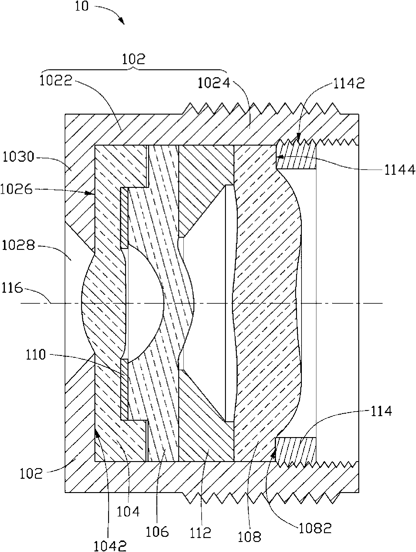
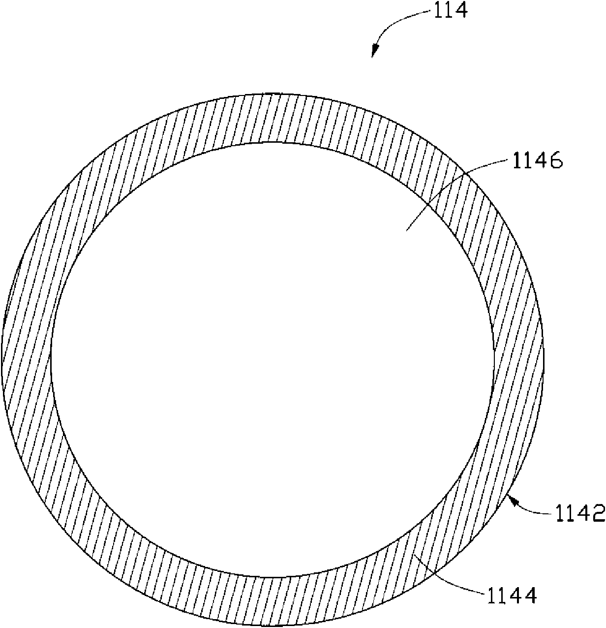
[0014] see figure 1 , the lens module 10 of the preferred embodiment of the present invention includes a lens barrel 102 and a lens unit accommodated in the lens barrel 102 . The lens unit includes a first lens 104 , a shading sheet 110 , a second lens 106 , a spacer 112 , a third lens 108 and a positioning ring 114 in sequence from the object side to the image side. The lens unit has an optical axis 116 .

[0015] Lens barrel 102 has opposing first end 1022 and second end 1024 . The first end portion 1022 has a bearing portion 1030 , and the bearing portion 1030 defines a through hole 1028 , and the through hole 1028 allows external light to enter the lens barrel 102 . The first end 1022 has an inner surface 1026, and the second end 1024 is provided with external threads and internal threads at the same time, the external threads are used to cooperate wi...


PUM


Abstract

The invention relates to a lens module, which comprises a lens barrel, a lens unit and a positioning ring, wherein the lens barrel is provided with a first end part and a second end part which are opposite, the first end part is provided with a bearing part, and the second end part is provided with internal threads; the lens unit is accommodated in the lens barrel, and is borne on the bearing part; and the positioning ring is provided with external threads, attached with the lens unit, and is matched with the lens barrel through the threads so as to fix the lens unit in the lens barrel. In addition, the invention also provides a method for assembling the lens module.

Description

technical field [0001] The invention relates to optical imaging technology, in particular to a lens module and an assembly method thereof. Background technique [0002] With the development of optical imaging technology, lens modules are widely used in various imaging devices such as digital cameras and video cameras (see Capturing images with digital still cameras, Micrc, IEEE Volume: 18, issue: 6, Nov.-Dec .1998 Page(s): 14-19). Portable electronic devices such as mobile phones and notebooks integrated with lens modules are favored by many consumers. [0003] A lens module 20 in the prior art such as image 3 As shown, it includes a lens barrel 202 , and a first lens 204 , a shading sheet 210 , a second lens 206 , a spacer 212 and a third lens 208 are sequentially arranged in the lens barrel 202 from the object side to the image side. Optical elements such as lenses in the lens barrel 202 are generally fixed in the lens barrel 202 by dispensing glue. [0004] However, i...

Claims


Application Information

Patent Timeline
Patent Type & Authority Applications(China)
IPC IPC(8): G02B7/02
CPCG02B7/022G02B13/0035G02B13/001G02B7/021
Inventor 吴承勋
Owner HONG FU JIN PRECISION IND (SHENZHEN) CO LTD
Why Eureka
Try Eureka