

Driving structure and optical anti-shake camera
A technology of driving structure and driving components, which is applied in the direction of image communication, TV, color TV parts, etc. It can solve the problems of unable to take pictures or video, poor imaging quality, etc., and achieve the effect of uniform force, good effect and reduced volume
- Summary
- Abstract
- Description
- Claims
- Application Information
AI Technical Summary
Problems solved by technology
Method used
Image

Examples
Embodiment 1
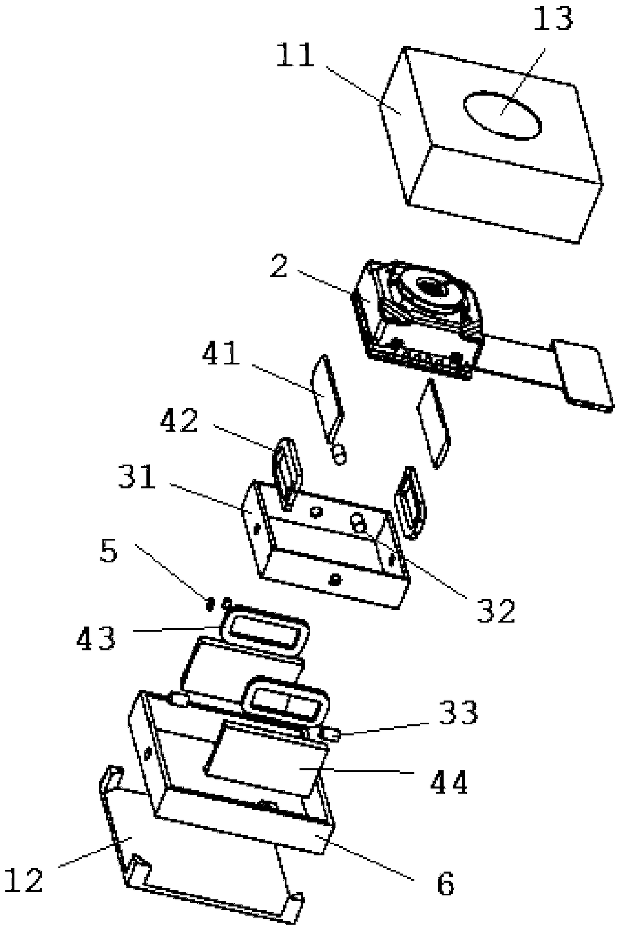
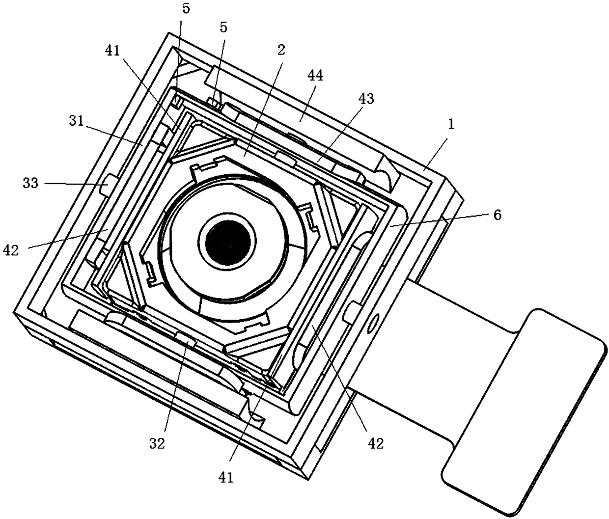
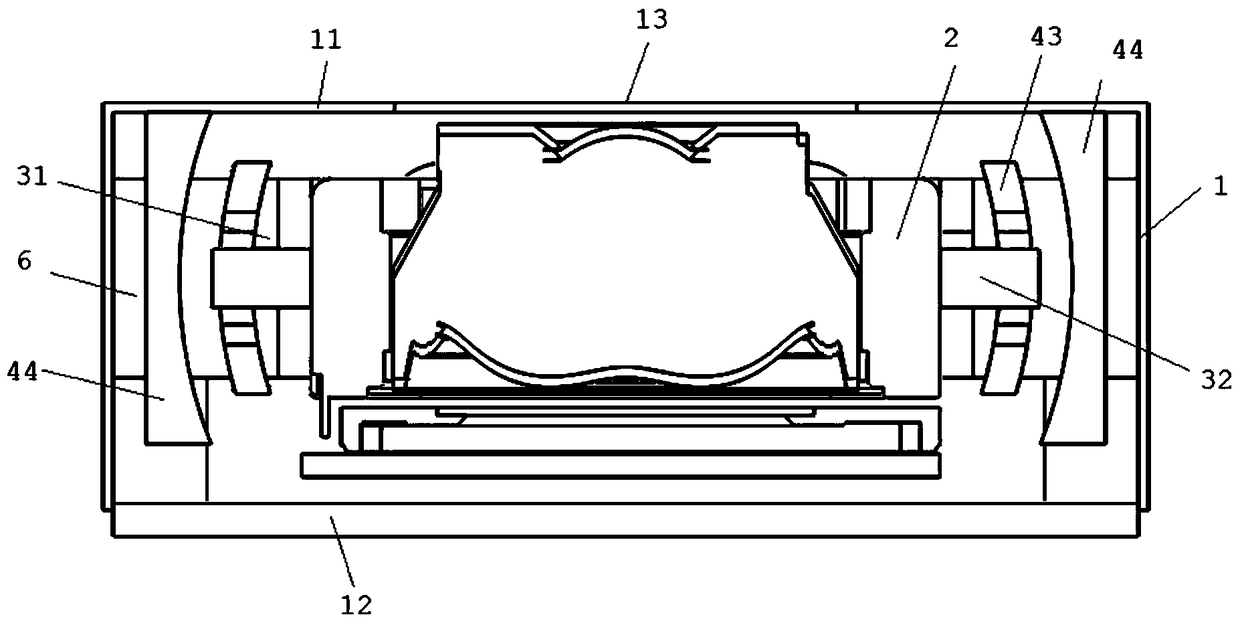
[0029] Drive structure of the present invention, refer to Figure 1 to Figure 4 , including a seat body 1, a module body 2, a module driving assembly, a deflection assembly, an anti-shake driving assembly and a monitoring element 5.
[0030] The seat body 1 includes an upper cover 11 and a base 12. The upper end of the upper cover 11 has an opening 13 for light to pass through. The group drive assembly, deflection assembly, anti-shake drive assembly and monitoring part 5 are arranged in the accommodation cavity, and after the base 12 is connected to the upper cover 11, the module body 2, the module drive assembly, the deflection assembly, the anti-shake drive assembly and the monitor Part 5 closes the accommodating chamber. In order to facilitate the installation of the deflection assembly, a frame body 6 for connecting the deflection assembly is also provided on the inner wall of the seat body 1 .
[0031] The module body 2 is arranged in the base body 1, and has a fixed im...
Embodiment 2
[0043] The optical image stabilization camera of this embodiment includes the drive structure, image sensor and lens in Embodiment 1. The image sensor is fixedly arranged on the module body 2 of the driving structure; the lens is arranged on the module body 2 which can move toward or away from the image sensor.
[0044] During autofocus, the module drive assembly drives the lens toward or away from the image sensor along the optical axis; during optical image stabilization, the first coil 42 drives the first magnet 41 to move, driving the module body 2 equipped with the first coil 42 to rotate around the second When the rotation axis rotates, the second magnet 44 drives the second coil 43 to move, and drives the spacer 31 and the module body 2 to rotate around the second rotation axis, so as to realize the deflection movement of the module body 2 away from the optical axis.
PUM
 Abstract
Description
Claims
Application Information