Tool holder attachment structure

a tool holder and attachment structure technology, applied in the field of tool holder, can solve the problems of reducing the mechanical properties of the tool holder, requiring a micron error or less, and requiring the use of recent machining tools, so as to reduce the concentration of elastic stress, reduce vibration and attachment failure, and simplify manufacturing

Inactive Publication Date: 2007-10-23
PASCAL ENG
View PDF18 Cites 42 Cited by
  • Summary
  • Abstract
  • Description
  • Claims
  • Application Information

AI Technical Summary

Benefits of technology

[0034]According to another embodiment of the present invention there is provided a tool holder attachment structure, for removably securing a tool holder with a tool to a main shaft of a machining tool, comprising: at least a shank on the tool holder, the shank having at least a tapered outer perimeter surface, the main shaft including a tapered attachment hole, means for elastically securing the shank in the attachment hole of the main shaft and eliminating vibration and attachment failure during a use of the machining tool and the tool holder attachment, at least a plurality of elastic engagement pieces in the means for elastically securing, the elastic engagement pieces arrayed concentrically around an inner perimeter section of the attachment hole, the elastic engagement pieces extending away from the main shaft and elastically abutting the tapered outer perimeter surface of the shank during an insertion of the shank into the attachment hole, and the elastic engagement pieces elastically deforming in at least a first radial direction during the insertion and the use, whereby the means for elastically securing enables the elastic engagement pieces to absorb a plurality of use vibrations while maintaining a secure attachment between the main shaft and the tool holder.
[0035]According to another alternative embodiment of the present invention there is provided a tool holder attachment structure, further comprising: a plurality of ring-shaped grooves on the inner perimeter section of the attachment hole, the plurality of ring-shaped grooves arrayed alternatingly with respective the elastic engagement pieces in an axial direction along the inner perimeter section of the attachment hole, the plurality of ring-shaped grooves including smooth radius contours at bottom portions thereof, thereby minimizing elastic stress concentration, and the plurality of elastic engagement pieces extending integrally from the main shaft, thereby simplifying manufacturing and assembly of the main shaft and the tool holder with a uniform force.
[0036]According to another alternative embodiment of the present invention there is provided a tool holder attachment structure, wherein: the plurality of elastic engagement pieces, each having a first length, extends from each respective ring-shaped groove to respective the inner perimeter section of the tapered attachment hole, an end of each the elastic engagement piece arrayed in a plane parallel to the tapered outer perimeter surface of the shank, whereby each the elastic engagement piece contacts the tapered outer perimeter surface simultaneously during the insertion to provide easy alignment and tight attachment, and the first length of each respective the elastic engagement piece being dependant upon a position on the tapered attachment hole relative to the tapered outer perimeter surface of the shank.

Problems solved by technology

Unfortunately, high machining precision, of 1 micron error or less, is demanded from recent machining tools.
Consequently, the tool holder and the main shaft (rotating at high speeds) undergo undesirable rotary vibrations, which are a factor in degrading machining precision.
Unfortunately, due to machining tolerances in the tapered hole of the main shaft and the tool holder, the tool can heat up during use, resulting in detrimental thermal expansion of both the main shaft and the tool holder.
Detrimental thermal expansion makes it impossible to secure the entire shank of the tool holder firmly and tightly against the tapered hole of the main shaft.
It is also impossible to abut the flange of the tool holder tightly to the end surface of the main shaft while having the shank of the tool holder tightly secured in the tapered hole of the main shaft.
Consequently, conventional tool holders are not designed to abut its flange on the end surface of the main shaft.
As a result of this narrowing, the tapered outer perimeter surface of the sleeve cannot be tightly fitted and secured against the tapered hole.
This makes it difficult to have a uniform contact force over the entire perimeter and provide secure coupling with the inner surface of the tapered hole.
As a further detriment to this design, an increased number of parts is required and the structure is correspondingly complex, thus increasing manufacturing costs.
Unfortunately, the structure of the shank is the same as previous conventional shank structures, and roughly the same problems therefore exist as in conventional tool holders.

Method used


Image

  • Tool holder attachment structure
  • Tool holder attachment structure
  • Tool holder attachment structure

Examples


Embodiment Construction

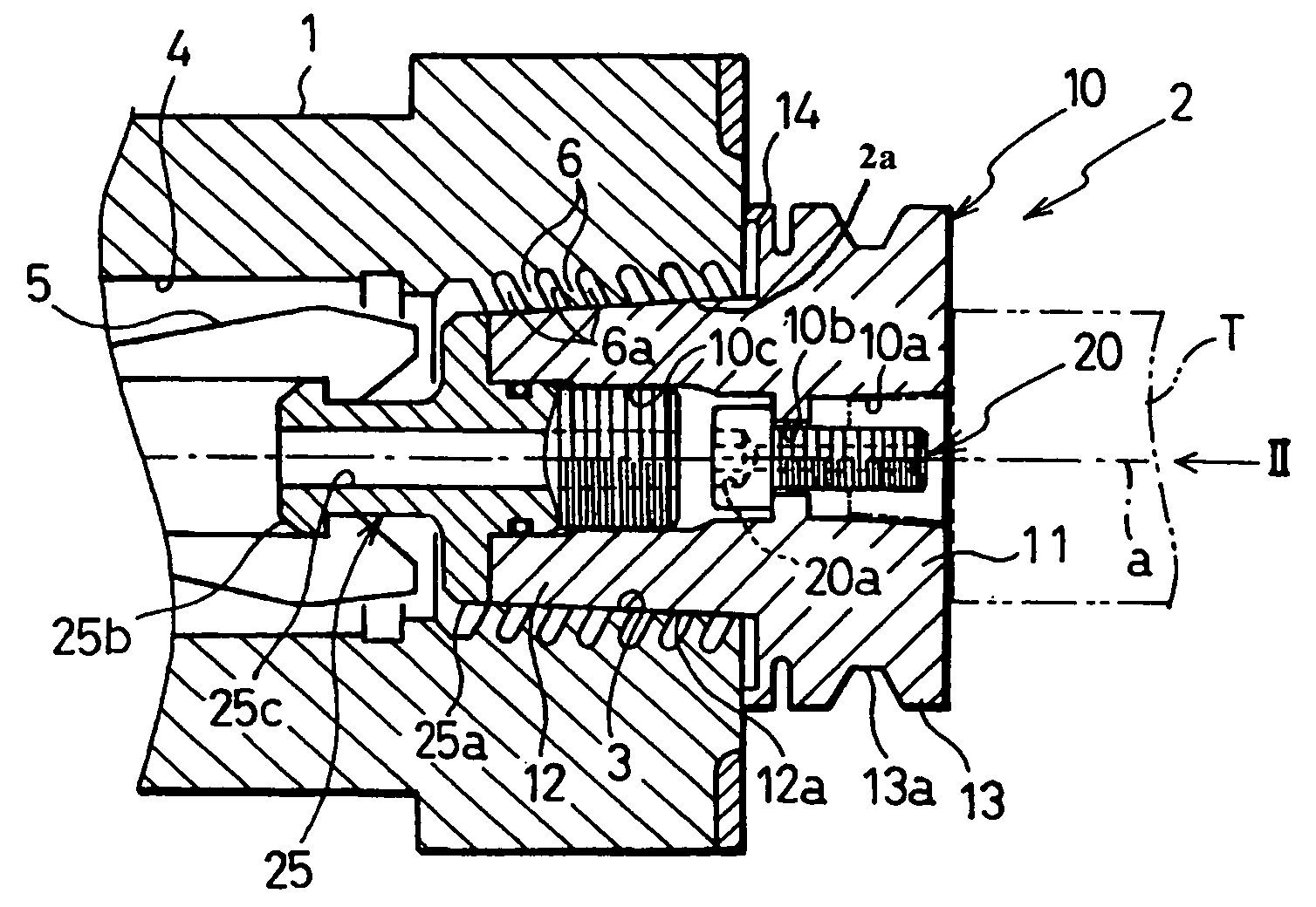
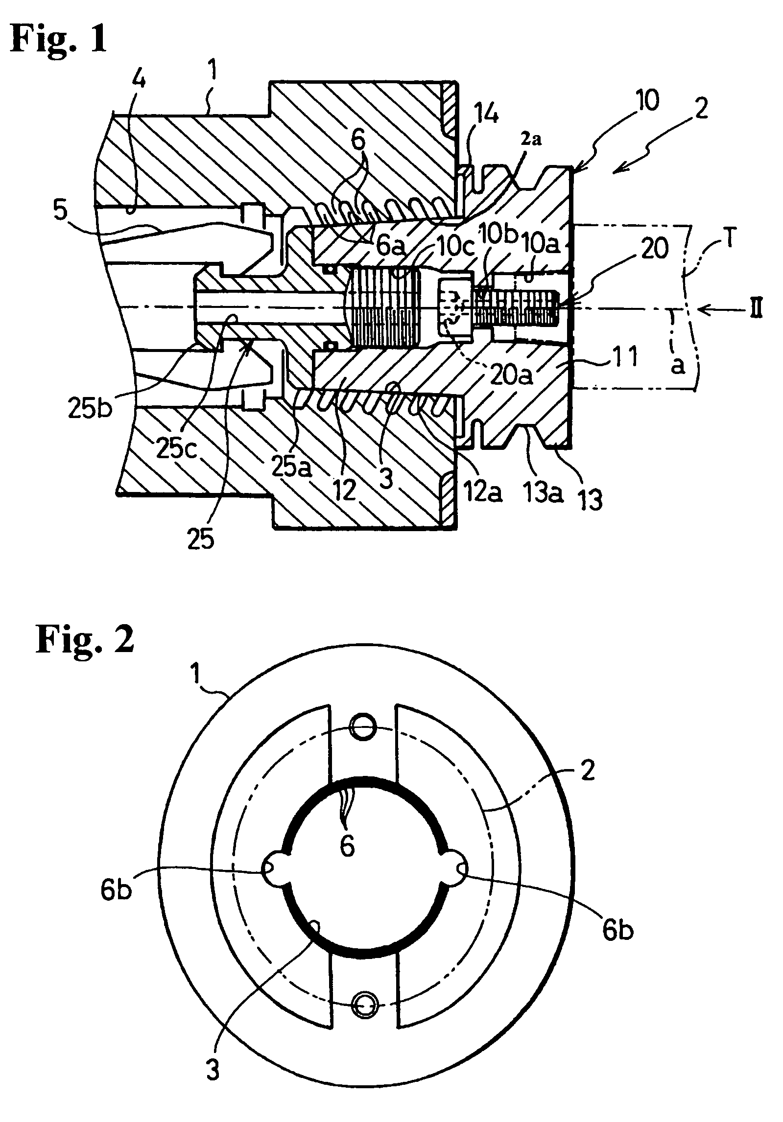
[0055]Referring now to FIG. 1, a tool holder 2, includes a main holder unit 10, mounted on a main shaft 1 of a machine tool (not shown). A tapered attachment hole 3 extends inward from an end of main shaft 1. Attachment hole 3 is larger at a first end of main shaft 1 and narrows towards a center axis, as shown. An axial center of attachment hole 3 is aligned with an axial center a of main shaft 1.

[0056]An end surface of main shaft 1 is a flat surface perpendicular to axial center a. A holding hole 4, inside main shaft 1, extends continuously with attachment hole 3. A collet 5, is disposed at the end of a draw bar extending from a retraction mechanism (not shown). Collet 5 retracts and secures a shank 12 of tool holder 1 in attachment hole 3 of main shaft 1.

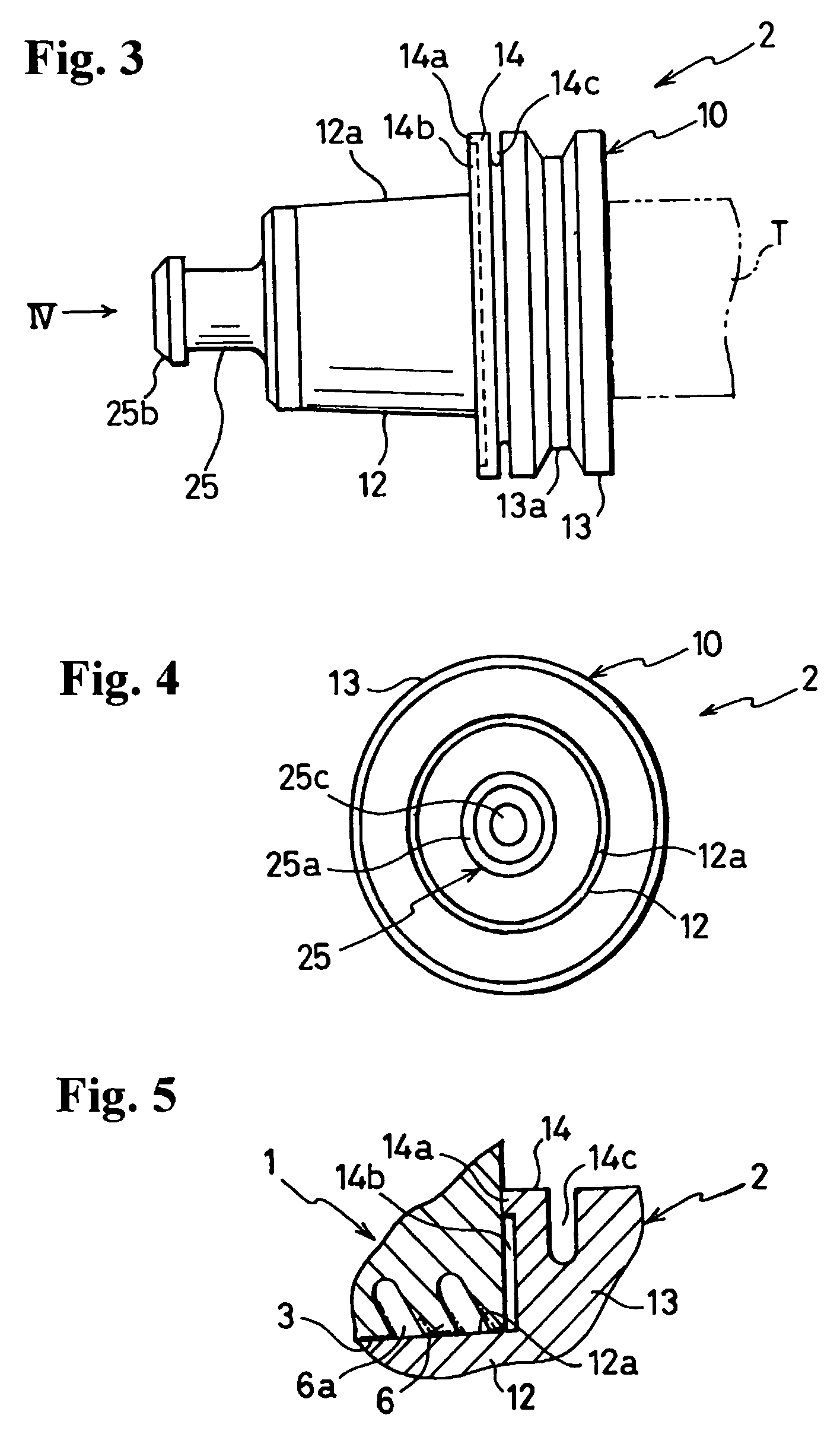
[0057]Tool holder 2 includes main holder unit 10, a locking bolt 20, and a pull stud 25. Main holder unit 10 includes a tool support 11 for attaching a tool T, a shank 12 having a tapered perimeter surface 12a, and a flange 13.

[00...


PUM

PropertyMeasurementUnit
perimeteraaaaaaaaaa
elasticaaaaaaaaaa
rotational torqueaaaaaaaaaa

Abstract

A main shaft includes a plurality of elastic engagement pieces arrayed along an outer perimeter of an attachment hole. During and after assembly, the elastic engagement pieces elastically abut at least an outer surface of a tapered shank in a tool holder and deform slightly in a radial direction. The elastic engagement pieces provide uniform engagement force between the main shaft and the tool holder over a broad surface area. An elastic flange provides additional elastic engagement and easy separation from the main shaft. Together, the elastic engagement pieces and elastic flange reliably engage and securely attach the main shaft to the tool holder while aiding disengagement.

Description

[0001]The present application claims the benefit of International Application No. PCT / JP00 / 02339, filed Apr. 10, 2000, which is hereby incorporated by reference in its entirety.BACKGROUND OF THE INVENTION[0002]1. Field of the Invention[0003]The present invention relates to a tool holder that reliably secures a tool along a main shaft of a machine tool.[0004]2. Description of the Related Art[0005]Conventionally a tool holder is attached to the end of a main shaft to support a tool. This type of attachment is used in various machine tools including drill presses, milling machines, and machining centers.[0006]With conventional tool holders, a main shaft rotates the tool to perform machining on a workpiece. Since the tool holder is removably attached to the main shaft, the main shaft is equipped with a retraction mechanism to draw in and secure a shank of the tool holder.[0007]Conventional tool holders include a tool support section for attaching a tool, a shank including a tapered oute...

Claims


Application Information

Patent Timeline
Patent Type & Authority Patents(United States)
IPC IPC(8): B23Q3/12B23B31/00
CPCB23B31/006B23B2265/32Y10T409/304312Y10T409/309352B23B2270/06B23B31/08B23Q7/046
Inventor MIYAZAWA, HIROSHI
Owner PASCAL ENG
Why Eureka
Try Eureka