Speed-adjusting-type permanent-magnet drive system

A permanent magnet drive and speed regulation technology, applied in electric components, electromechanical transmission devices, electrical components, etc., can solve the problems of shortening equipment life, vibration, wear, etc., to avoid harmonics, eliminate vibration, and stabilize speed regulation. Effect

Active Publication Date: 2010-10-20
ANSHAN QINYUAN ENERGY SAVING EQUIP MFG
View PDF3 Cites 36 Cited by
  • Summary
  • Abstract
  • Description
  • Claims
  • Application Information

AI Technical Summary

Problems solved by technology

[0002] At present, most of the coupling mechanisms widely used in the industry are rigid connections. Due to the complex and changeable operation of the system, no matter how to ensure the strict alignment of the two axes, the equipment will vibrate after a period of operation, thereby accelerating wear and shortening the life of the equipment.

Method used


Image

  • Speed-adjusting-type permanent-magnet drive system
  • Speed-adjusting-type permanent-magnet drive system
  • Speed-adjusting-type permanent-magnet drive system

Examples


Embodiment Construction

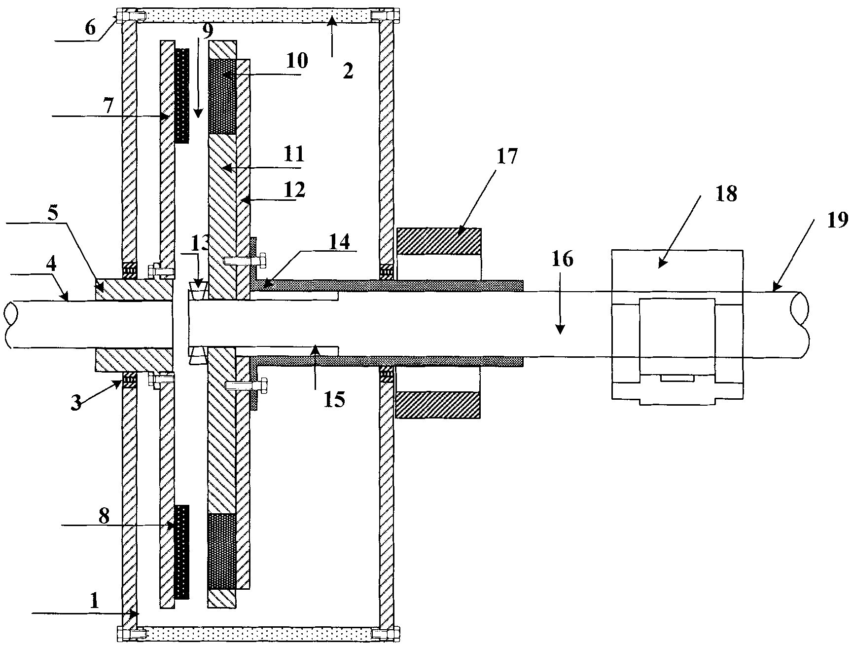
[0016] See figure 1 , a speed-regulating permanent magnet drive system, including a conductor rotor (first rotor), a permanent magnet rotor (second rotor), a lead screw adjuster, a conductor rotor fixedly connected to an input shaft and rotating in unison with the input shaft, and a permanent magnet The rotor is floatingly installed on the additional shaft section of the output shaft, which drives the shaft section to rotate and transmits the torque to the output shaft; there is a gas gap between the conductor rotor and the permanent magnet rotor.

[0017] The first rotor consists of a disc-shaped steel frame 7 and a copper conductive ring 8 fixed on the disc-shaped steel frame 7 , the disc-shaped steel frame 7 is connected with the shaft sleeve 5 and fixed on the input shaft 4 .

[0018] The second rotor consists of an aluminum mounting plate 11 , a steel support plate 12 and a permanent magnet 10 . See image 3 , The permanent magnet 10 is embedded in the mounting plate 11...


PUM


Abstract

The invention relates to a speed-adjusting-type permanent-magnet drive system, comprising a conductor rotor (a first rotor), a magnetic rotor (a second rotor) component and a lead screw regulator, wherein the conductor rotor (the first rotor) is arranged on an input shaft; the magnetic rotor (the second rotor) is arranged on an output shaft; the conductor rotor comprises a disk-shaped steel frame and a copper conducting ring; the surface of a steel plate is provided with the copper conducting ring; the opposite surfaces of a permanent-magnet rotor and the conductor rotor are embedded with permanent magnets; the gap of the opposite surfaces of the conductor rotor and the permanent-magnet rotor can adjust an axial air clearance; and the conductor rotor and the permanent-magnet rotor are coupled by the magnetic force. When the conductor rotor rotates, the permanent-magnet rotor also rotates along the same direction with the conductor rotor due to the coupling action of the magnetic force; the conductor rotor (the first rotor) is fixedly connected with the input shaft; the permanent-magnet rotor (the second rotor) is connected with the output shaft by a shaft section; the regulator is arranged on the shaft section; and the air clearance between the disk surfaces of the two rotors can be adjusted by the regulator, thus changing the torque and the rotating speed and achieving the purpose of speed adjustment.

Description

technical field [0001] The invention relates to a speed-regulating permanent magnet drive system, which belongs to high-efficiency and energy-saving speed regulators. Background technique [0002] At present, most of the coupling mechanisms widely used in the industry are rigid connections. Due to the complex and changeable operation of the system, no matter how to ensure the strict alignment of the two axes, the equipment will vibrate after a period of operation, which will accelerate wear and shorten the life of the equipment. The use of permanent magnetic coupling can eliminate the rigid connection between the motor shaft and the load shaft, so that the vibration between the load and the motor is isolated and does not affect each other, allowing greater centering errors. When the equipment is overloaded, it can also protect the equipment and provide soft Start function. At present, frequency conversion speed regulation is widely used in industrial sites, which generates ...

Claims


Application Information

Patent Timeline
Patent Type & Authority Applications(China)
IPC IPC(8): H02K51/00
Inventor 王大志马忠威王旭江宁崔箫周玮仑
Owner ANSHAN QINYUAN ENERGY SAVING EQUIP MFG
Why Eureka
Try Eureka