Method and system for determining position and orientation of an object

A technology for determining method and orientation, applied in the field of movable units, can solve problems such as the increase of failure probability, and achieve the effect of reducing power consumption, improving accuracy and alleviating technical requirements

Inactive Publication Date: 2008-03-12
BEAMRIDER
View PDF1 Cites 30 Cited by
  • Summary
  • Abstract
  • Description
  • Claims
  • Application Information

AI Technical Summary

Problems solved by technology

Here, the problem or probability of failure increases with distance, so there is also a limit to the maximum achievable operating distance

Method used


Image

  • Method and system for determining position and orientation of an object
  • Method and system for determining position and orientation of an object
  • Method and system for determining position and orientation of an object

Examples


Embodiment Construction

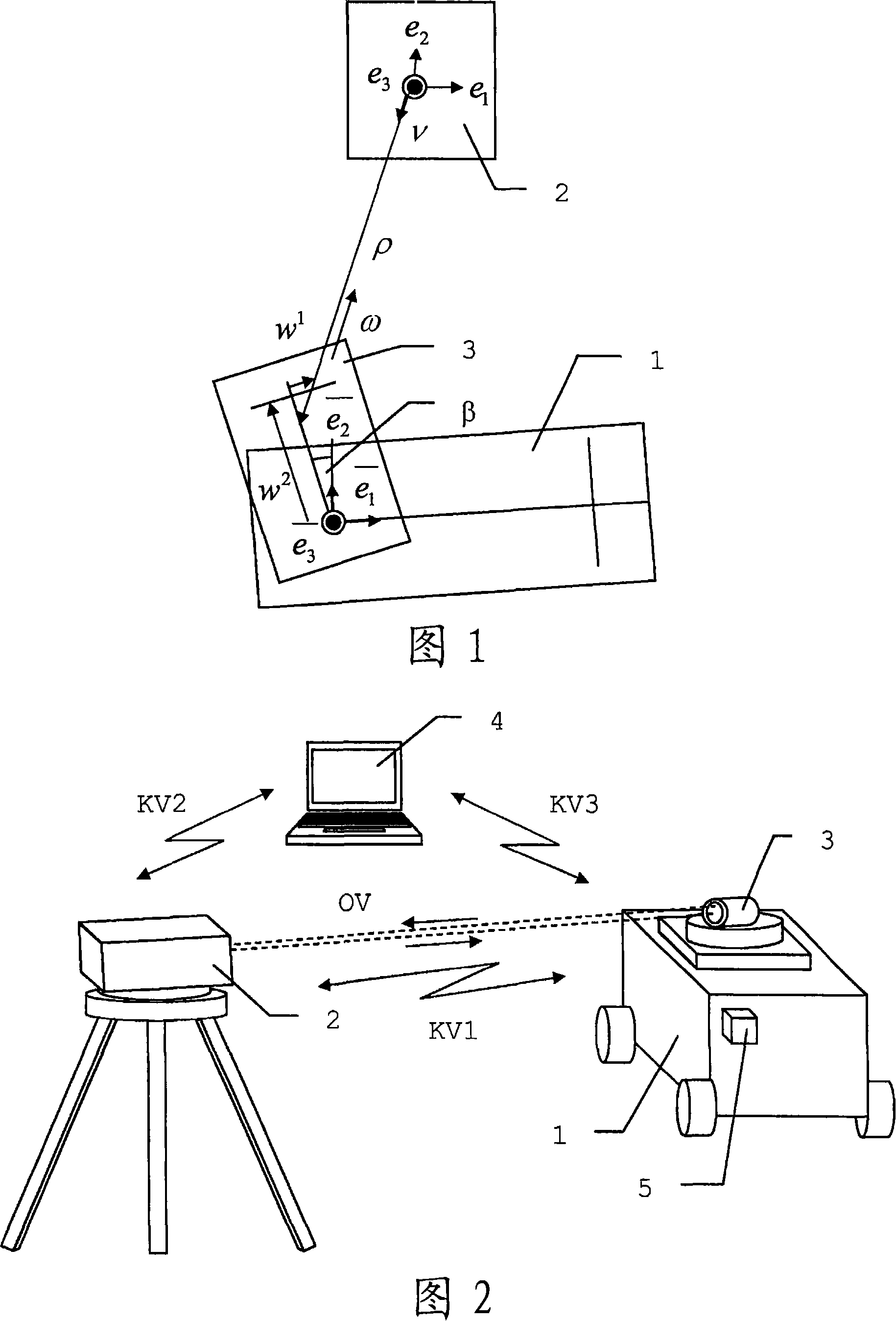
[0044] Figure 1 shows the geometrical relationships on which the orientation determination method is based. On the carrier part 1 of the mobile unit, a receiver 3 is mounted rotatably about a fixed axis, wherein the axis is oriented orthogonally to the optical axis. For the sake of clarity, the illustrations are shown in plan view and without inclination to the horizontal. In general, however, another axis can also be realized for vertical adjustment of the receiver 3 . The laser is emitted by the scanning unit 2 and scanned over an angular range until the receiver 3 is detected and its distance is measured. From this, the distance and angle to the impact point or reflection point on the receiver 3 and thus the position of the receiver 3 are determined. The direction of incidence of the radiation is determined by the receiver 3 so that an orientation relative to this direction and thus relative to the scanning unit 2 can be deduced. These two systems (i.e. scanning unit 2 a...


PUM


Abstract

The invention relates to a positioning method for determining the position and orientation of a mobile unit having a receiver (3'), whereby the receiver (3') is detected by a scanner (2'), said scanner (2') determining at least the distance and a direction in relation to the receiver (3'). The radiation emitted by the sensor is detected by the receiver (3') and the direction of incidence of radiation and the direction of incidence of radiation in relation to an axis of reception are derived while an offset of the incident radiation in relation to the axis of reception (EA) is determined. Position and orientation of the unit are derived from at least the distance, the direction in relation to the receiver (3'), the offset and the direction of incidence as the position information and the unit is optionally controlled via the optical connection (OV).

Description

technical field [0001] The invention relates to a position determination method according to the preamble of claim 1 , a mobile unit according to the preamble of claim 9 , a position determination system and a computer program product. Background technique [0002] In numerous geodetic applications, systems and methods for determining the orientation (ie, position and / or orientation) of instruments used are employed. Starting from a position determined with such a system, further measurements which are associated with this position and usually also require knowledge of the spatial orientation of the measuring device are usually carried out subsequently. In this case, in principle, the orientation of the device can also be deduced from the determined positions of two or more points. For measurement technology applications, 6 degrees of freedom (at least position and 3 degrees of freedom) of the hand-held measuring instrument must be determined in order to unambiguously deter...

Claims


Application Information

Patent Timeline
Patent Type & Authority Applications(China)
IPC IPC(8): G01S17/42
CPCG01C15/002G01S17/42
Inventor 贝亚特·埃比舍尔伯恩哈德·布劳内克彼得·基佩弗
Owner BEAMRIDER
Why Eureka
Try Eureka