
Probe assembly for a fluid condition monitor and method of making same

A component and state technology, applied in the field of sensors, can solve the problems of insufficient manufacturing cost, difficulty in setting electrode elements, difficulty in providing surface area and spacing, etc.

Inactive Publication Date: 2005-06-08
EATON CORP
View PDF1 Cites 9 Cited by
  • Summary
  • Abstract
  • Description
  • Claims
  • Application Information

AI Technical Summary

Problems solved by technology

A disadvantage of the probe device of the aforementioned Bauer et al. '281 patent is that it is difficult to support and shield the device from mechanical interference, such as when the probe is to be immersed in elevated temperature motor vehicle transmission fluid or engine lubricant. In the case of mechanical disturbances due to vibration or fluid movement such as splashes or pressure disturbances
[0003] Furthermore, the electrode elements in the probes described above have proven to be difficult to place, especially where the electrodes are formed of thin material deposited on a substrate, making it difficult to provide the required surface area and spacing, not robust enough and expensive to manufacture
[0004] Moreover, problems have been encountered in providing a sufficiently high signal-to-noise ratio for the above-mentioned types of probes in fluid monitoring of the impedance measurement type.

Method used


Image

  • Probe assembly for a fluid condition monitor and method of making same
  • Probe assembly for a fluid condition monitor and method of making same
  • Probe assembly for a fluid condition monitor and method of making same

Examples


Embodiment Construction

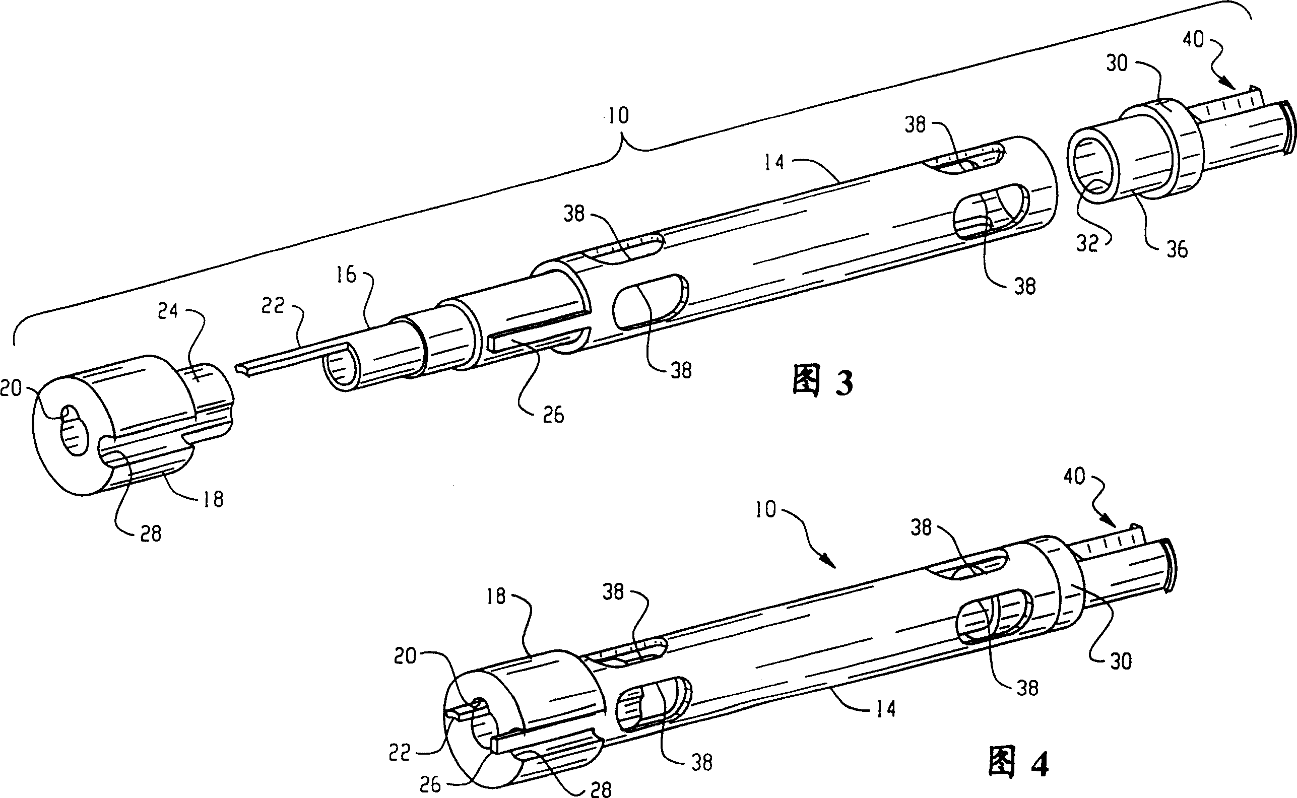
[0016] Referring to Figures 1 and 2, an embodiment of the present invention suitable for monitoring fluid in an automatic transmission of a motor vehicle, generally designated 10, includes a tubular inner electrode 12 having a certain The outer surface is distanced in length from the inner circumference of a tubular outer electrode 14 by a predetermined amount to provide a prescribed surface area for the electrodes spaced at known distances.

[0017] The inner electrode 12 has a reduced diameter portion 16 which is received within an end cap or sleeve 18 which has a passage 20 therethrough through which a connector terminal 22 extends, preferably axially Extended and shaped, and integrally formed as a member with the end portion of the internal electrode 12 .

[0018] The outer electrode 14 is received at the periphery of a reduced diameter portion 24 formed on the end cap 18 for maintaining the inner electrode 12 and the outer electrode 14 in the desired spaced apart relation...


PUM

PropertyMeasurementUnit
Surface areaaaaaaaaaaa
Wall thicknessaaaaaaaaaa
Diameteraaaaaaaaaa

Abstract

A probe assembly for real-time monitoring of fluid state in a sensor using impedance spectroscopy, the probe assembly has two closely spaced tubular concentric electrodes. When the pitch is in the range of about 0.15 to 0.55 mm, the surface area of ​​the electrodes is about 8.1 to 10.8 cm2. In one embodiment, a concentric tubular outer Faraday shield is used to monitor fluid within a non-metallic container. This probe assembly is especially useful for monitoring hydraulic fluids, including automatic transmission fluids and mineral-based engine oils used in diesel and gasoline engines.

Description

technical field [0001] The present invention relates to sensors for providing real-time electrical indications of the instantaneous state of fluids in an operating system. In particular, the present invention relates to fluid state monitoring in fluids used for engine lubrication and hydraulic actuation in power transmission devices such as automatic transmissions of motor vehicles. Background technique [0002] It is known, as described in U.S. Patent 6,278,281 in the name of R.A. Bauer et al. and assigned to the assignee of the present invention, to employ impedance spectroscopy or impedance spectroscopy at different frequencies related to bulk fluid impedance and surface impedance of electrodes. Measurements to determine the state of operating fluids over time and service. The fluid condition monitor described above employs a pair of electrodes arranged with its interleaved unit in a generally planar array or as spaced apart parallel plates and arranged to be immersed in...

Claims


Application Information

Patent Timeline
IPC IPC(8): G01N27/02F01M11/10G01N27/22
CPCG01N27/226G01N27/00G01N27/08
Inventor 邹廉强J·E·汉森V·E·施泰达
Owner EATON CORP
Learn More