Digital low-and-medium-frequency self-adaptive three-phase half-controlled rectifying device and triggering method thereof

A semi-controlled rectification and digital technology, applied in the direction of output power conversion device, AC power input conversion to DC power output, electrical components, etc., can solve the problems of complex design, many components, heavy equipment weight, etc., to achieve the elimination of Disturbing, easy-to-use effects

Active Publication Date: 2011-07-20
THE 715TH RES INST OF CHINA SHIPBUILDING IND CORP
View PDF3 Cites 9 Cited by
  • Summary
  • Abstract
  • Description
  • Claims
  • Application Information

AI Technical Summary

Problems solved by technology

However, the commonly used analog integrated trigger circuit is easily affected by various factors of power generation equipment. When the frequency changes greatly, the parameters of the peripheral circuit need to be adjusted, the design is complicated and the debugging is difficult.
The existing digital trigger circuit requires three synchronous signals as a reference for the controllable rectification of three-phase AC power, and uses a synchronous transformer for isolation and phase matching. The weight of the equipment is large, the components are many and the cost is high

Method used


Image

  • Digital low-and-medium-frequency self-adaptive three-phase half-controlled rectifying device and triggering method thereof
  • Digital low-and-medium-frequency self-adaptive three-phase half-controlled rectifying device and triggering method thereof
  • Digital low-and-medium-frequency self-adaptive three-phase half-controlled rectifying device and triggering method thereof

Examples


Embodiment Construction

[0025] The present invention will be further described below in conjunction with the drawings and embodiments:

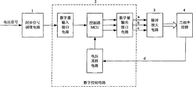
[0026] The invention discloses a digital mid-low frequency adaptive three-phase half-controlled rectifier device and a triggering method thereof. Such as figure 1 As shown, the device includes a synchronous signal conditioning circuit 1, and the output signal is sent to the digital input interface of the digital control circuit 2 to measure the signal period and start the trigger signal; the digital control circuit includes a controller MCU, a digital input Interface circuit, digital output interface circuit and voltage sampling circuit, the controller MCU according to the period of the synchronization signal and the error signal e calculated by the PID digital controller control angle Three trigger signals of a, b, and c are generated, and the output signal triggers the three-phase half-controlled bridge 4 through the pulse amplifier circuit 3. When working, the AC v...


PUM


Abstract

The invention discloses a digital low-and-medium-frequency self-adaptive three-phase half-controlled rectifying device and a triggering method thereof. The device mainly comprises a synchronous signal conditioning circuit, a digital control circuit and a pulse amplifying circuit. After passing through optically coupled isolation, alternating-current voltage signals are sent into the digital control circuit by the conditioning circuit; and a controller MCU (Microcontroller Unit) calculates the period according to the sent synchronous signals and updates a control angle so as to generate three paths of triggering signals. The pulse amplifying circuit amplifies the signals and then triggers a three-phase half-controlled bridge so as to implement controllable rectification. In the method, three phases are triggered in sequence according to a software program designed by the controller in the digital control circuit; and after a sampling voltage value and a preset voltage value are compared, the control angle is calculated by a PID (Proportion Integration Differentiation) digital controller so as to implement the closed-loop control of the rectified voltage. The invention implements the triggering rectification by frequency self-adaptive digital phase shifting within the working range of low-and-medium-frequency voltage. The invention has the characteristics of high symmetry degree of the output pulse, high anti-interference capability and high response speed, and the synchronous signal conditioning circuit is compact and reliable.

Description

Technical field [0001] The invention belongs to the technical field of power electronic equipment switch device control, and is mainly a digital mid-low frequency adaptive three-phase half-controlled rectifier device and a trigger method thereof. Background technique [0002] When the AC power output by the permanent magnet generator is not stabilized, when the load changes, the generator speed changes greatly, causing the amplitude and frequency of the three-phase AC power to change within a relatively large range. In order to obtain a stable output voltage, a more stable DC voltage is generally obtained through controllable rectification and then inverter is performed. However, the commonly used analog integrated trigger circuit is susceptible to various factors of the power generation equipment. When the frequency changes greatly, the peripheral circuit parameters need to be adjusted, the design is complicated and the debugging is difficult. The existing digital trigger circu...

Claims


Application Information

Patent Timeline
Patent Type & Authority Applications(China)
IPC IPC(8): H02M7/219
Inventor 何卫彬徐凯
Owner THE 715TH RES INST OF CHINA SHIPBUILDING IND CORP
Why Eureka
Try Eureka