Generator support plenum

a technology of generators and plenums, which is applied in the direction of machines/engines, mechanical energy handling, mechanical apparatus, etc., can solve the problems of insufficient electrical service, noisy use in rv parks, and insufficient electrical service, so as to reduce noise, eliminate the vibration of rvs, and reduce the risk of fire

Inactive Publication Date: 2009-01-27
PIERCEY III GERALD S
View PDF113 Cites 30 Cited by
  • Summary
  • Abstract
  • Description
  • Claims
  • Application Information

AI Technical Summary

Benefits of technology

[0008]The invention relates to a plenum that (1) cools hot exhaust exiting an engine-generator set, (2) channels engine cooling air and air for combustion into the generator enclosure, (3) mounts or supports the generator neatly inside a pickup toolbox or other enclosure, and (4) reduces noise. In one embodiment, a generator support truck for example, the plenum fits within a containment box which is the toolbox of a pickup and opens through openings formed in a wall of the box. (By “wall” is meant the box's bottom, lid or any of its upright walls.) In another embodiment the plenum supports the toolbox itself within which the generator is contained and communicates through openings through a toolbox wall. In a third embodiment the plenum and toolbox are combined into a single unit. Removal of the generator to the tow vehicle, away from the RV, reduces the risk of fire and eliminates the vibration of the RV. Exhaust can be directed away from the RV and any neighbor.
[0009]In the case where an engine-generator set must be located in the generator compartment of an RV, the containment box and plenum of the invention can still improve the problems of noise and hot exhaust gas being wrongly directed. In several exemplary preferred embodiments, the box and plenum with air intake ducts opening to atmosphere draw in air to aspirate the engine and cool the engine and generator, while cooling air being exhausted is intermixed with hot exhaust before expulsion from the generator-containing box. In one case the box protrudes through the floor of the RV generator compartment and has openings into the plenum and out of the plenum through sidewalls just below the floor of the compartment. In another case floor openings in an RV generator compartment align with openings into the air intake duct and out of the air outlet duct.
[0010]Hot exhaust from the internal combustion engine is mixed with warmed cooling air that, while warm, is nevertheless very much cooler than the exhaust, and the intermixed gasses are dispersed from an outlet duct formed by the plenum. Diffusers of various shapes and designs can be connected to the tailpipe of the internal combustion engine driving the generator. Holes along the length of the diffuser emit the hot exhaust into the cooler, cooling air that is on its way to atmosphere. Thus intermixed, the gaseous output from the box that houses the engine-generator set is far cooler and safer than hot exhaust.

Problems solved by technology

Generators used with recreational vehicles (RVs), on boats and those mounted on trucks for use at a worksite more often than not are intrusively noisy and direct hot exhaust fumes where they should not.
In older RV parks, for example, insufficient electrical service often is available for when the park is well-filled with newer RVs that boast a multiplicity of electrical appliances, air conditioners and the like.
Generally these are too noisy for use in a crowded RV park, and often gasoline engine exhaust is directed out the side directly towards the next door neighbor.
When the generator is in or on the RV itself, vibrations as well as noise will plague the RV occupant.
Moreover, an on-board generator is (or can be) a fire hazard.
Likewise, at a worksite, noise and noxious exhaust fumes can, again, annoy persons in the neighborhood of a truck-mounted generator.
Emission of very hot exhaust from the internal combustion engine of an engine-generator set is a hazard to neighbors, pets and close-by objects in a tightly populated camp site or RV park.
A further problem that has arisen in connection with engine-generator sets used to power electrical appliances on houseboats, yachts and the like has been the collection of carbon monoxide in living and sleeping quarter.
In at least one locality where vacationers regularly rent houseboats, sickness and fatalities have occurred.

Method used


Image

  • Generator support plenum
  • Generator support plenum
  • Generator support plenum

Examples


Embodiment Construction

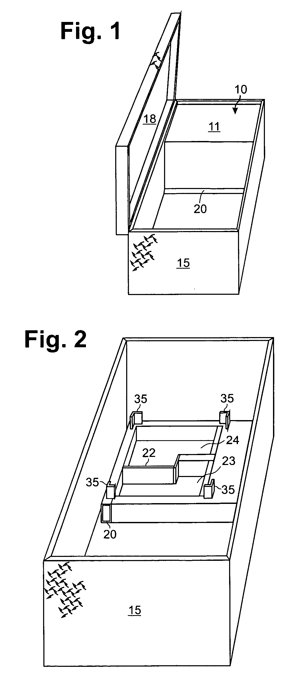
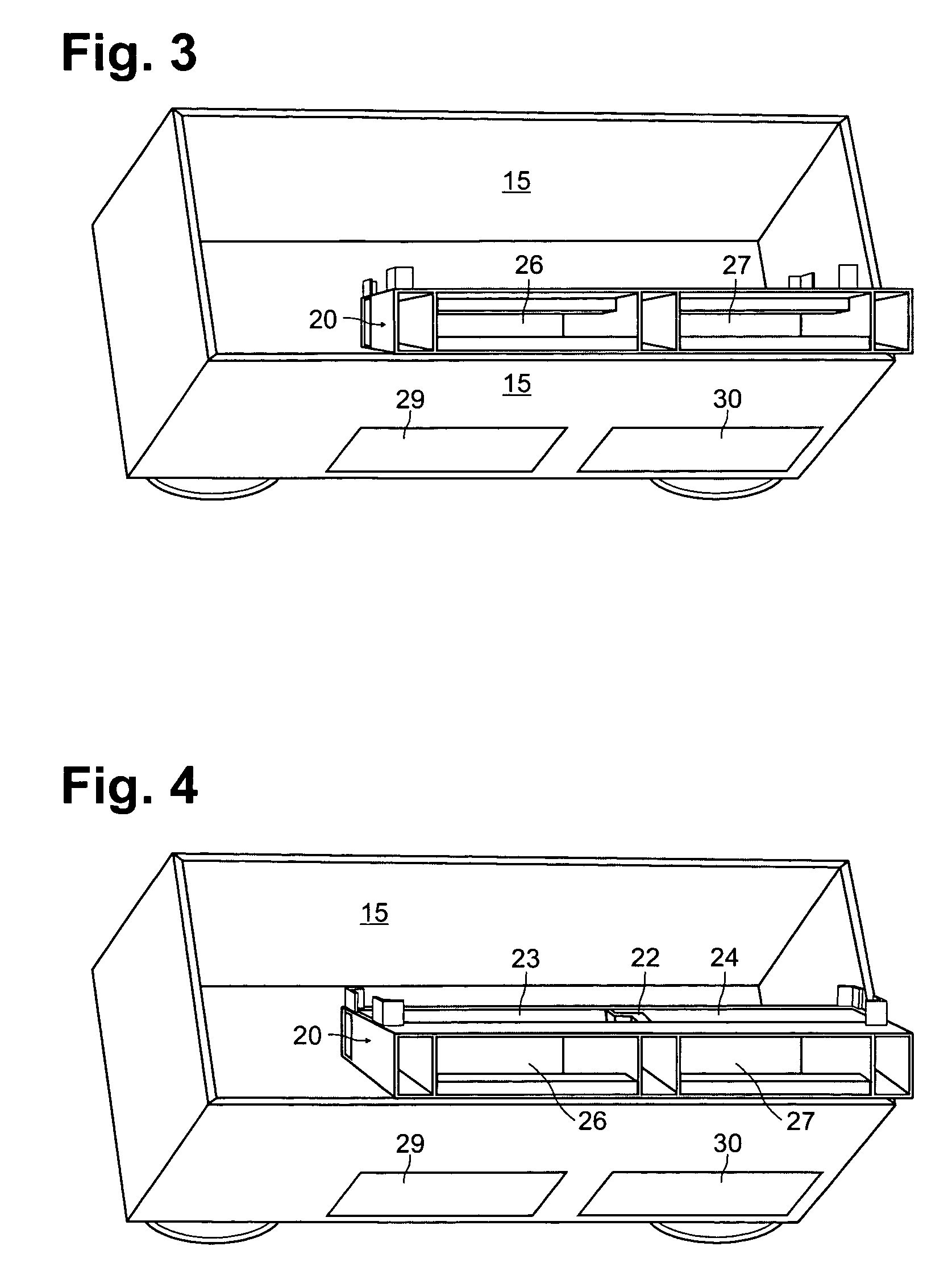
[0037]In FIG. 1 an engine-generator set 10 supported by the plenum 20 in a toolbox 15. The engine-generator set 10 is referred to on occasion here as the generator 10 or the “generator” as such usage is common. A central wall 22 (FIG. 2) conforms a pair of ducts 23 and 24 to the gas intake and output provisions (not shown) of the engine-generator set 10 having an outer case 11.

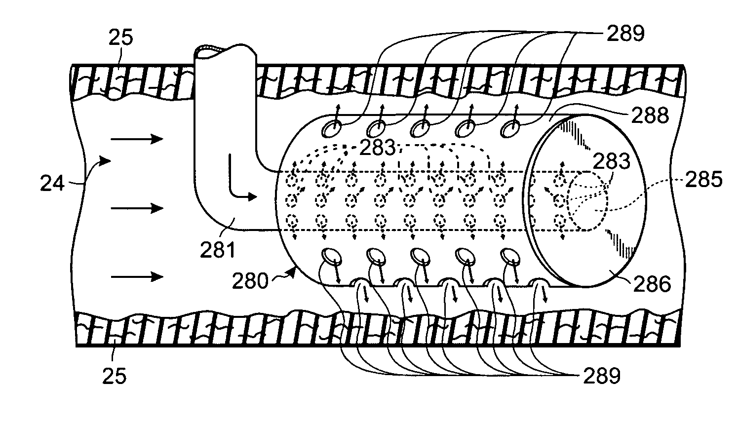
[0038]The duct 23 of FIG. 2 is the air intake duct and fits under openings in the case 11 (FIG. 1) through which the generator 10 draws cooling air into the generator enclosure and over the internal combustion engine and generator. It, the duct 23, also fits under and opens into an ignition air intake opening in the generator case 11 that provides air for combustion within the internal combustion engine that drives the generator.

[0039]The duct 24 is the air outlet duct that allows the escape of the cooling air and also the exhaust of the generator driving engine. Into the duct 24 flows the cooling air exiting ...


PUM


Abstract

A generator support plenum for a engine-generator set for installation on a pickup truck in an RV or on a boat, for example, sits in or under or forms a part of an enclosure for the engine-generator set and defines cool air flow paths into the set for cooling the engine and generator and aspirating the engine. The plenum also defines a warm air outlet duct for escape of the cooling air. In the outlet duct a diffuser couples to the exhaust of the engine to mix hot exhaust with the much cooler escaping cooling air that has passed over the engine and generator. The diffuser eliminates the effect of the extreme hot exhaust gas and muffles the engine sound. Insulation coating the internal surfaces of the plenum further suppresses engine noise.

Description

CROSS REFERENCE TO RELATED APPLICATIONS[0001]This application claims priority from the provisional patent application Ser. No. 60 / 470,011 filed May 12, 2003 in the name of Gerald S. Piercey, III entitled “Compressor Mount Plenum” incorporated herein by reference.FIELD OF THE INVENTION[0002]This invention relates to an intake and exhaust plenum for a generator and more particularly to a plenum that supports the generator.BACKGROUND[0003]Generators used with recreational vehicles (RVs), on boats and those mounted on trucks for use at a worksite more often than not are intrusively noisy and direct hot exhaust fumes where they should not. In older RV parks, for example, insufficient electrical service often is available for when the park is well-filled with newer RVs that boast a multiplicity of electrical appliances, air conditioners and the like. Where that is the case, RV owners typically crank up their own generators. Generally these are too noisy for use in a crowded RV park, and o...

Claims


Application Information

Patent Timeline
Patent Type & Authority Patents(United States)
IPC IPC(8): F02B63/04H02K7/18F02B77/11F02C1/00F03C1/00
CPCF02B77/11
Inventor PIERCEY, III, GERALD S.
Owner PIERCEY III GERALD S
Why Eureka
Try Eureka