Display device with elastic spacers having varying widths and hardness

a technology of elastic spacers and display devices, applied in the field of display devices, can solve the problems of irregularities in image display, and liquid crystal display panel warping, and achieve the effects of reducing the warping of liquid crystal display panels, facilitating deformation, and low hardness of spacers

Active Publication Date: 2008-05-27
JAPAN DISPLAY INC +1
View PDF7 Cites 40 Cited by
  • Summary
  • Abstract
  • Description
  • Claims
  • Application Information

AI Technical Summary

Benefits of technology

[0027]In a liquid crystal display device configured in this manner, by varying the hardness of the spacers in the longitudinal direction thereof, as indicated in the configuration of Example (1), the transmission of a force from the frames to the liquid crystal display panel can be controlled, whereby the force on the display panel can be made uniform and warping of the liquid crystal display panel can be significantly reduced.
[0028]FIG. 3 is a characteristic diagram relating to a case where rubber is selected as the material of the elastic spacers and which shows the relationship of the width w of the spacer and a deformation amount δ thereof with respect to pressure F in a case where the hardness of the rubber is 20. If the hardness is different, the characteristics change, but the characteristics shown in FIG. 3 are shifted almost substantially linearly. Namely, when the hardness of the spacers is low, it becomes that much easier for them to deform, and, due to that deformation, it becomes easier to avoid warping resulting from a force on the liquid crystal display panel from the frames.
[0030]Also, changing the width of the elastic spacers as a means to vary the hardness along the longitudinal direction thereof has the effect that the elastic spacers become extremely easy to manufacture.

Problems solved by technology

However, it has become apparent that, in a liquid crystal display panel configured in this manner, warping of the liquid crystal display panel occurs and that irregularities in the image display arise due to this warping.
As a result of pursuing the cause of this problem, it has been discovered that the problem results from the elastic frames interposed between the liquid crystal display panel and the support frames, and it has become apparent from this that, when the force from the support frames is transmitted to the liquid crystal display panel, warping occurs in the liquid crystal display panel, because the force is not uniform.
It was also discovered that this warping is a problem shared in common with display devices that include a panel and support frames.

Method used


Image

  • Display device with elastic spacers having varying widths and hardness
  • Display device with elastic spacers having varying widths and hardness
  • Display device with elastic spacers having varying widths and hardness

Examples


first embodiment

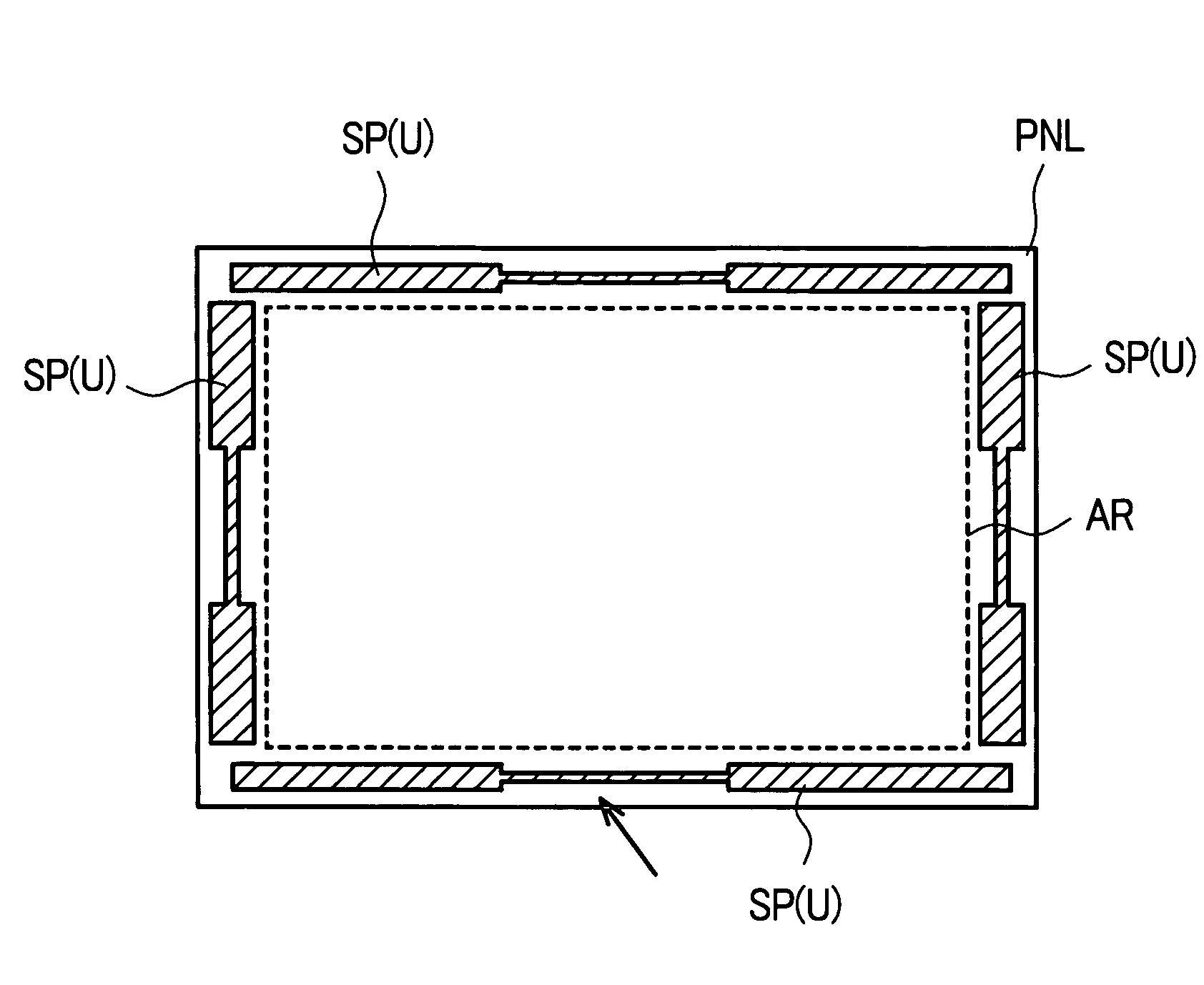
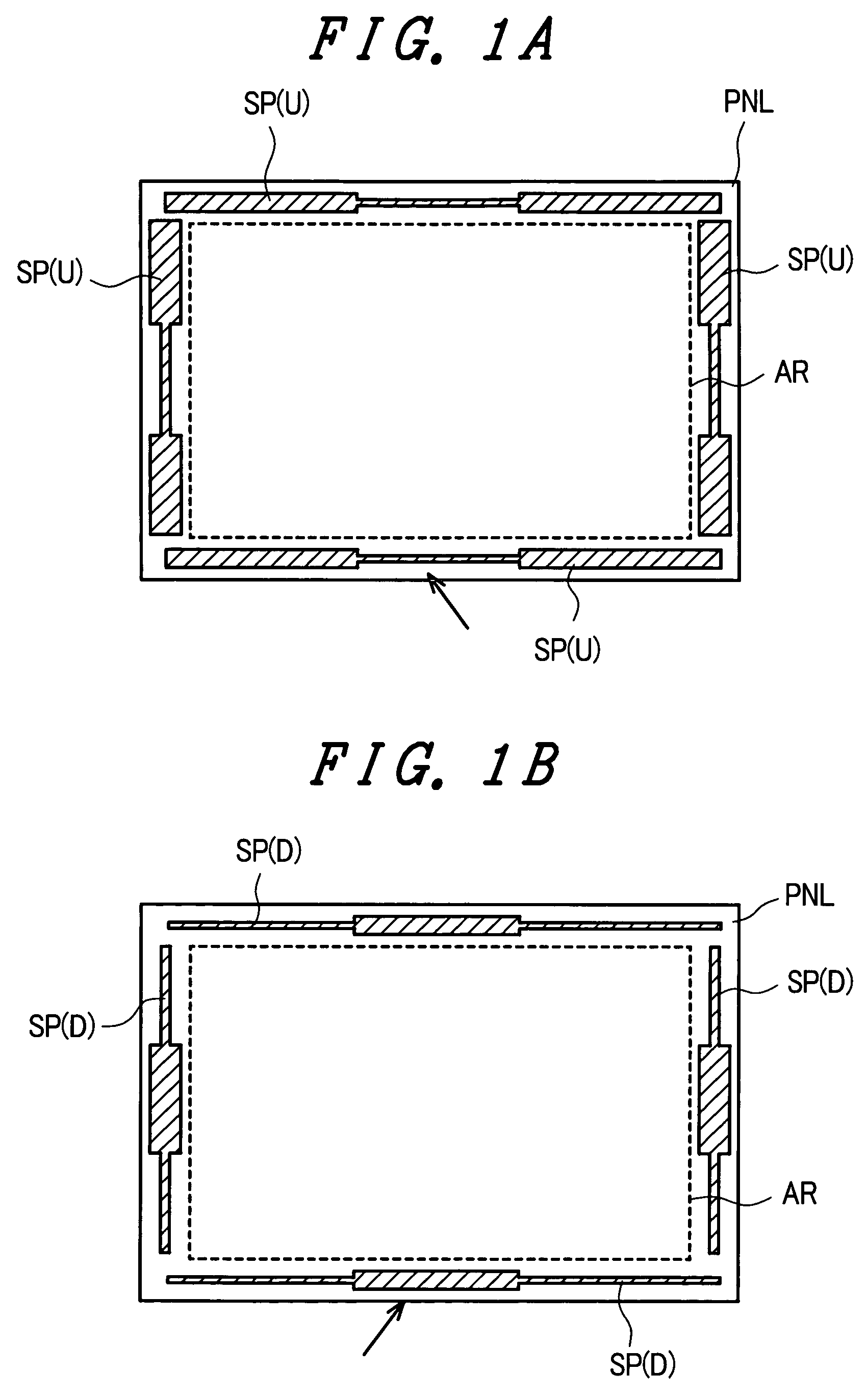
[0056]FIGS. 1A and 1B are diagrams showing an embodiment of the spacers SP. FIG. 1A shows the spacers SP(U) that are positioned between the liquid crystal display panel PNL and the upper frame UF, and FIG. 1B shows the spacers SP(D) that are positioned between the liquid crystal display panel PNL and the mold frame MF. In both FIGS. 1A and 1B, the spacers are depicted so as to illustrate their positional relations with respect to the liquid crystal display panel PNL.

[0057]The spacers SP(U) that are positioned between the liquid crystal display panel PNL and the upper frame UF are disposed between the outer contour of the liquid crystal display panel PNL and the outer contour of the effective display region AR thereof, and, as seen in FIG. 1A, there are four spacers that extend linearly along each side of the effective display region AR.

[0058]Additionally, each of the spacers SP(U) is tripartitioned along the longitudinal direction thereof, with the center portion thereof (e.g., the ...

second embodiment

[0062]FIGS. 4A and 4B are diagrams showing another embodiment of the spacers SP. FIG. 4A shows the spacers SP(U) that are positioned between the liquid crystal display panel PNL and the upper frame UF, and FIG. 4B shows the spacers SP(D) that are positioned between the liquid crystal display panel PNL and the mold frame MF. In both FIGS. 4A and 4B, the spacers are depicted so as to illustrate their positional relations with respect to the liquid crystal display panel PNL.

[0063]The spacers SP(U) positioned between the liquid crystal display panel PNL and the upper frame UF are disposed between the outer contour of the liquid crystal display panel PNL and the outer contour of the effective display region AR thereof, and, as seen in FIG. 4A, there are four spacers that extend linearly along each side of the effective display region AR.

[0064]Additionally, each of the spacers SP(U) is tripartitioned along the longitudinal direction thereof, with the center portion thereof (e.g., the port...

third embodiment

[0068]FIG. 5 is a diagram showing another embodiment of the spacers SP, for example, the spacers SP(U) that are positioned between the liquid crystal display panel PNL and the upper frame UF. The spacers SP(U) positioned between the liquid crystal display panel PNL and the upper frame UF are disposed between the outer contour of the liquid crystal display panel PNL and the outer contour of the effective display region AR thereof, and, as seen in FIG. 5, there are four spacers that extend linearly along each side of the effective display region AR.

[0069]Of these, each spacer of the pair of spacers SP positioned at portions corresponding to the longer sides of the effective display region AR is tripartitioned along the longitudinal direction thereof, with the center portion thereof (e.g., the portion indicated by arrow A in the drawing) being narrowly formed and both side portions being widely formed. Also, each of the pair of spacers (e.g., indicated by arrow B in the drawing) positi...


PUM

PropertyMeasurementUnit
widthaaaaaaaaaa
hardnessaaaaaaaaaa
mechanical stressaaaaaaaaaa

Abstract

A display device has a display panel, a frame, and an elastic spacer arranged on the periphery of the display panel in parallel to the edge of the display panel. The elastic spacer is arranged between the display panel and the frame, and the hardness of the elastic spacer is varied along the length-side direction of the elastic spacer.

Description

BACKGROUND OF THE INVENTION[0001]The present invention relates to a display device; and, more particularly, to a technique for effecting support for a display panel in a display device so as to reduce warping of the display panel.[0002]A display device, such as a liquid crystal display device, includes a liquid crystal display panel for displaying an image. The liquid crystal display panel is formed of a pair of substrates, such as glass sheets, that are disposed so as to mutually oppose each other via liquid crystal, with numerous pixels being disposed in the spreading direction of the liquid crystal.[0003]A pair of electrodes is disposed in each pixel of the liquid crystal display panel, and the light transmissivity of the liquid crystal of the pixels is controlled by an electric field generated between these electrodes. For this reason, a light source is necessary in order to perceive an image on the liquid crystal display panel. Ordinarily, a backlight is disposed at the back su...

Claims


Application Information

Patent Timeline
Patent Type & Authority Patents(United States)
IPC IPC(8): G02F1/1333G02F1/133G02F1/1339G09F9/30G09F9/35
CPCG02F1/13394G02F2201/54
Inventor TSUBOKURA, MASAKIYATSU, YASUHARUFUMIKURA, TATSUYUKITOMIZUKA, YOSHITERU
Owner JAPAN DISPLAY INC
Why Eureka
Try Eureka