Liquid crystal display device

a liquid crystal display and liquid crystal technology, applied in non-linear optics, instruments, optics, etc., can solve the problems of difficult optically compensating liquid crystal cells completely, gradation reversal cannot be prevented in the down direction of the screen, and light leakage, etc., to minimize the reduction of dark room contrast, reduce the effect of reflection performance and simple constitution

Active Publication Date: 2006-09-28
FUJIFILM CORP
View PDF9 Cites 70 Cited by
  • Summary
  • Abstract
  • Description
  • Claims
  • Application Information

AI Technical Summary

Benefits of technology

[0010] The present invention has been made by taking account of those various problems and an object of the present invention is to provide an IPS-type liquid crystal display device assured of good antireflection performance with minimized reduction of dark room contrast and despite a simple constitution, remarkably improved in not only the display quality but also the viewing angle.

Problems solved by technology

In this system, since the liquid crystal stands up with respect to the substrate at the black display, birefringence is generated due to liquid crystal molecules when the screen is viewed from the oblique side, and light leakage occurs.
However, it is very difficult to optically compensate the liquid crystal cell completely without problem even by using liquid crystal molecules, and there is a problem that gradation reversal cannot be prevented in the down direction of the screen.
In the case of applying an antiglare film to an IPS-mode liquid crystal display device, it has been found from studies by the present inventors that even when optical compensation is made in the liquid crystal display device, if an antiglare film having an insufficient effect of preventing projection of an image due to reflection of outside light is applied, a problem such as reduction in the dark room contrast arises.

Method used


Image

  • Liquid crystal display device
  • Liquid crystal display device
  • Liquid crystal display device

Examples


first embodiment

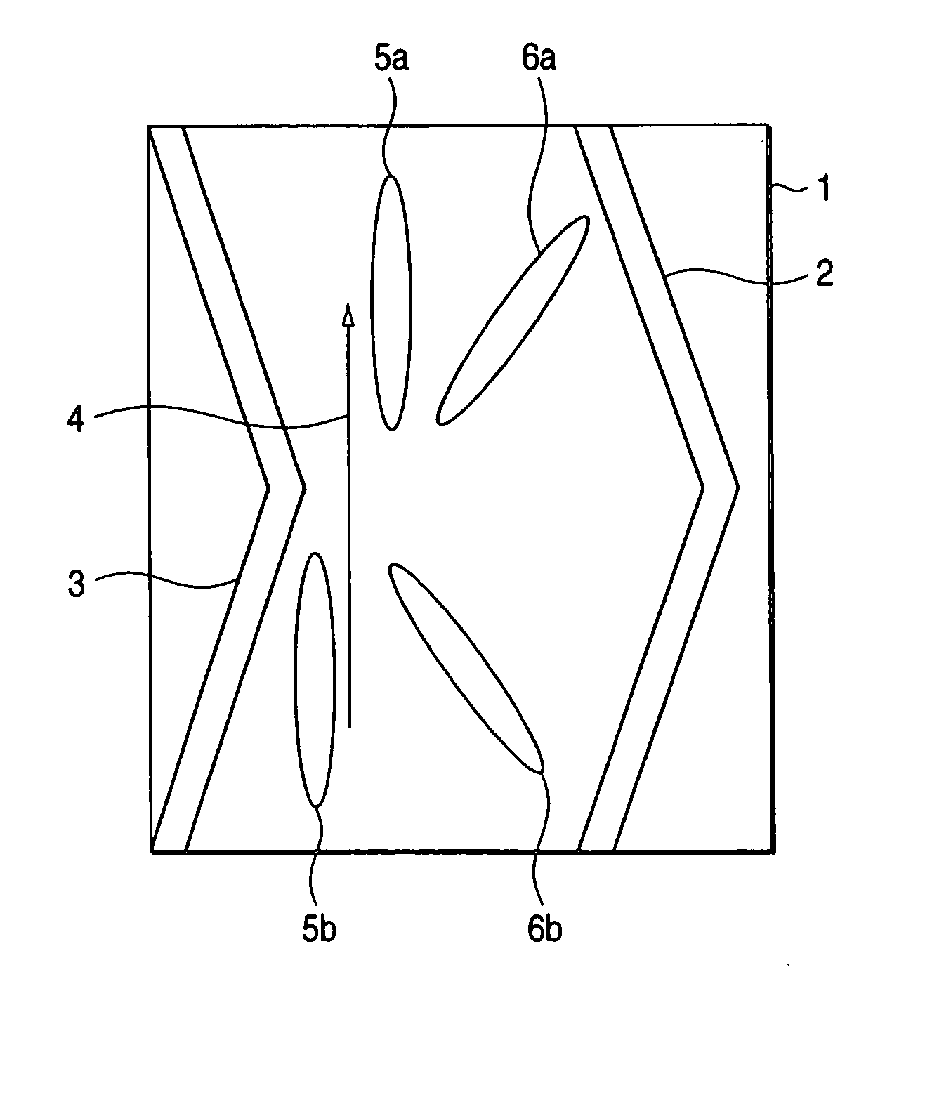
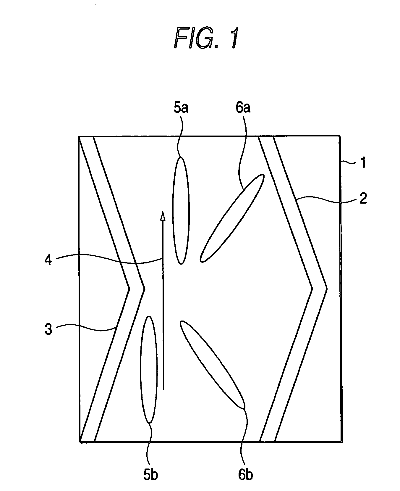
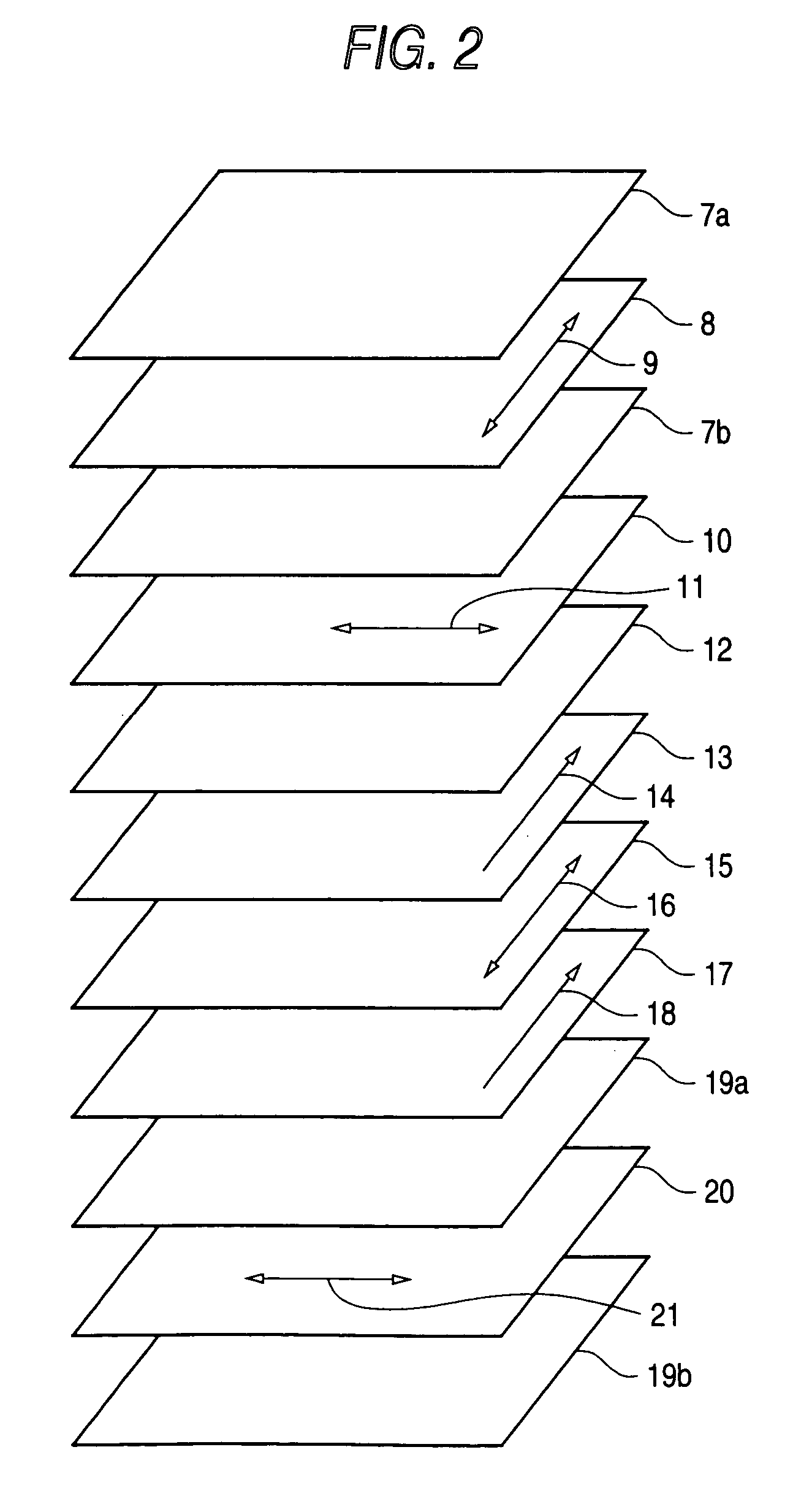
[0068] The embodiment of the present invention is described in detail below by referring to the drawings. FIG. 1 is a schematic view showing an example of the pixel region in the liquid crystal display device of the present invention. FIGS. 2 and 3 each is a schematic view showing the first embodiment of the liquid crystal display device of the present invention.

[0069] The liquid crystal display device shown in FIG. 2 comprises polarizing films 8 and 20, a first retardation region 10, a second retardation region 12, and a liquid crystal cell comprising a pair of substrates 13 and 17 and a liquid crystal layer 15 interposed therebetween. The polarizing films 8 and 20 are each sandwiched by protective films 7a and 7b and by protective films 19a and 19b, respectively.

[0070] In the invention, protective film 7a is the first protective film, Protective Film 19b is the second protective film, whereby either of the first and second protective films is provided with an antiglare layer by ...

second embodiment

[0102] The second embodiment of the present invention is described in detail below by referring to the drawings. FIGS. 4 and 5 each is a schematic view showing the liquid crystal display device in the second embodiment of the present invention.

[0103] The liquid crystal display device shown in FIG. 4 comprises polarizing films 8 and 20, a first retardation region 10, a second retardation region 12, substrates 13 and 17, and a liquid crystal layer 15 interposed between the substrates. The constitution of the liquid crystal cell and the aligned state of the liquid crystal molecules in one pixel region of the liquid crystal layer 15 are the same as those in the first embodiment of the liquid crystal display device of the present invention.

[0104] The polarizing films 8 and 20 are each sandwiched by protective films 7a and 7b and by protective films 19a and 19b, respectively. The transmission axis 9 of the polarizing film 8 is arranged to be orthogonal to the transmission axis 21 of the...

examples

[0374] The characteristic features of the present invention are described below in greater detail by referring to Examples and Comparative Examples. The materials, amounts used, ratios, treatment contents, treatment procedures and the like used in the following Examples can be appropriately changed or modified without departing from the purport of the present invention. Accordingly, the scope of the present invention should not be construed as being limited to these specific examples. Unless otherwise indicated, the “parts” and “%” are on the mass basis.

[0375] As shown in FIG. 1, electrodes (reference numbers 2 and 3 in FIG. 1) were provided on one glass substrate to give a distance of 20 μm between adjacent electrodes, and a polyimide film is provided thereon as an alignment film and subjected to a rubbing treatment. The rubbing treatment was performed in the direction 4 shown in FIG. 1. A polyimide film was provide on one surface of one separately prepared glass substrate and use...


PUM

PropertyMeasurementUnit
hazeaaaaaaaaaa
hazeaaaaaaaaaa
hazeaaaaaaaaaa

Abstract

A liquid crystal display device comprising: a first protective film; a first polarizing film; an optical compensation region; a liquid crystal cell comprising a liquid crystal layer and a pair of substrates sandwiching the liquid crystal layer; a second polarizing film; and a second protective layer, in this order, wherein at a black display, liquid crystal molecules in the liquid crystal layer are aligned in parallel with surfaces of said pair of substrates, an antiglare layer is provided to at least one of the first protective film and the second protective layer, and the antiglare layer has a haze value attributable to internal scattering of from 5 to 35%, and a haze value attributable to surface scattering of from 1 to 10%.

Description

BACKGROUND OF THE INVENTION [0001] 1. Field of the Invention [0002] The present invention relates to a liquid crystal display device, more specifically, the present invention relates to a ferroelectric liquid crystal display device, an antiferroelectric liquid crystal display device and an in-plane switching-mode liquid crystal display device where the display is effected by applying a transverse electric field to a nematic liquid crystal aligned in the horizontal direction. [0003] 2. Description of the Related Art [0004] As for the liquid crystal display device, a system of interposing a liquid crystal layer comprising a nematic liquid crystal oriented in the twisted alignment between two orthogonal polarizing plates and applying a vertical electric field to the substrate, namely, a so-called TN-mode, is being widely used. In this system, since the liquid crystal stands up with respect to the substrate at the black display, birefringence is generated due to liquid crystal molecules...

Claims


Application Information

Patent Timeline
Patent Type & Authority Applications(United States)
IPC IPC(8): G02F1/1335
CPCG02F1/133502
Inventor SUZUKI, TAKATOFUKUDA, KENICHI
Owner FUJIFILM CORP
Why Eureka
Try Eureka