
Composition for forming anti-reflective coating for use in lithography

a technology of anti-reflective coating and composition, which is applied in the direction of resistive material coating, photosensitive material auxillary/base layer, synthetic resin layered products, etc., can solve the problems of affecting the performance of lithography, and reducing the efficiency of lithography, so as to reduce control the rate of crosslinking reaction , the effect of increasing the dry etching ra

Active Publication Date: 2005-01-13
NISSAN CHEM IND LTD
View PDF6 Cites 28 Cited by
  • Summary
  • Abstract
  • Description
  • Claims
  • Application Information

AI Technical Summary

Benefits of technology

The halogenated bisphenol A resins can be synthesized by a polycondensation of a halogenated bisphenol A with epichlorohydrin. The halogenated bisphenol A includes for example tetrabromobisphenol A or tetrachlorobisphenol A, and as goods on the market, halogenated bisphenol A resins having a halogen content of 46 to 52% and an epoxy equivalent of 330 to 700 g / eq are easily available.
The composition for forming anti-reflective coating according to the present invention can be used, depending on process condition, as a coating having a function for preventing a light reflection and a function for preventing an interaction between a substrate and a resist or preventing an adverse effect on the substrate by materials constituting the resist or materials generated in exposure to the resist.

Problems solved by technology

Along with this change, influences of random reflection and standing wave off a substrate have become serious problems.
Wiring delay has a more adverse effect on high-speed performance of LSI in LSI pattern rule having a fineness of 0.13 μm or less, and it becomes difficult to proceed an improvement in performance of LSI due to the present status of LSI process technique.
The merit of this method is advantages in lithographic process, while the demerit is disadvantages in etching process.
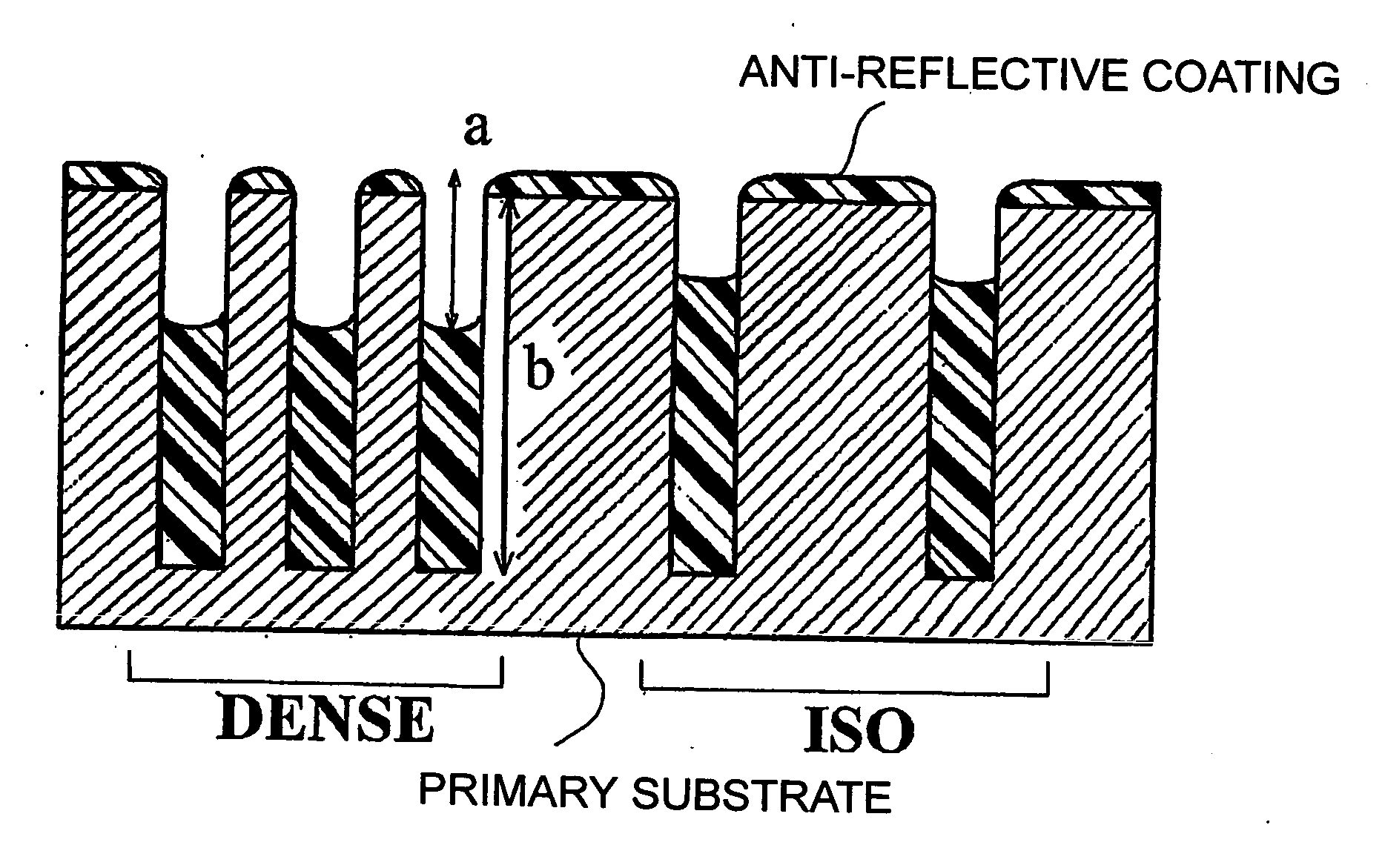
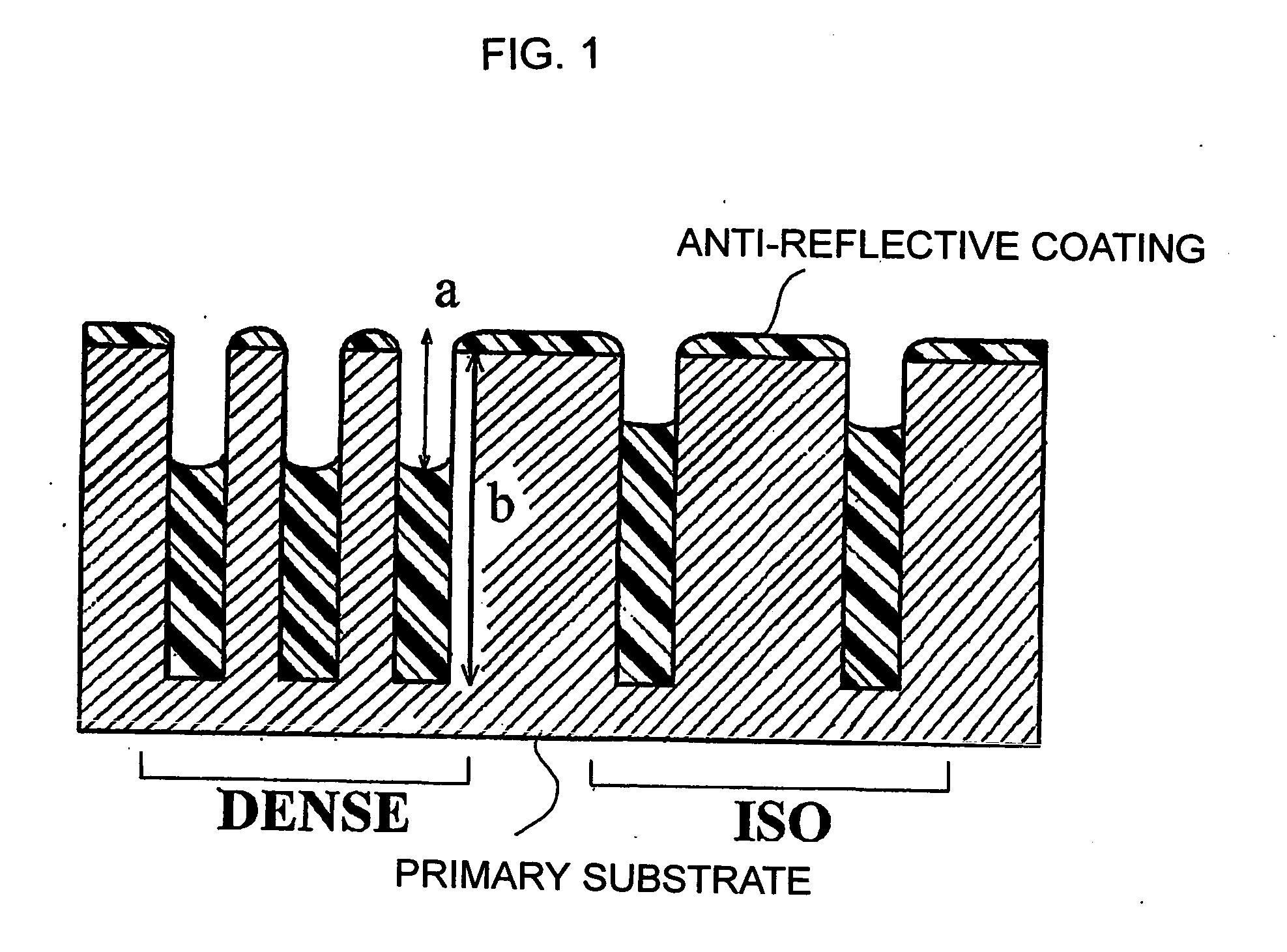
However, the demerit is disadvantages in lithography process in terms of an anti-reflective effect as a substrate having holes is not completely planarized.
However, the publication does not describe the formation of void or gap of air that has a tendency to exert an adverse effect when the anti-reflective coating is applied and that is an important point in a case where the material for forming anti-reflective coating is used in partial-fill type, and nor describe whether or not the thickness of the anti-reflective coating is constant regardless of the density of holes on a substrate.

Method used


Image

  • Composition for forming anti-reflective coating for use in lithography
  • Composition for forming anti-reflective coating for use in lithography
  • Composition for forming anti-reflective coating for use in lithography

Examples


synthesis example 1

A halogen-containing novolak epoxy resin (trade name: BREN-304 manufactured by Nippon Kayaku Co., Ltd.) was prepared. The resin had a weight average molecular weigh of 900 and a structure of formula (14).

After 100.0 g of the halogen-containing novolak epoxy resin was dissolved in 251.3 g of propylene glycol monomethyl ether, 67.6 g of 9-anthracenecarboxylic acid and 1.05 g of benzyltriethylammonium chloride were added. These compounds were reacted at 100° C. for 24 hours to obtain a polymer. The resulting polymer was subjected to GPC analysis and had a weight average molecular weight of 1,900 in terms of standard polystyrene. The structure of the resulting resin was shown by formula (15).

In formula (15), the molar ratio of n8: n5 in the whole polymer was 5:95, and n6 was 1.7.

synthesis example 2

After 26 g of glycidyl methacrylate monomer and 57 g of hydroxypropylmethacrylate were dissolved in 331 g of propylene glycol monomethyl ether to obtain a reaction solution, nitrogen was flowed into the reaction solution for 30 minutes. While the reaction solution was maintained at 70° C., 0.8 g of azobisisobutyronitrile (AIBN) as a polymerization initiator and 0.3 g of 1-dodecanethiol as a chain transfer agent were added therein and stirred under nitrogen atmosphere. After stirring for 24 hours, 0.1 g of 4-methoxyphenol as a short-stop was added therein. The resulting polymer was subjected to GPC analysis and had a weight average molecular weight of 36,400 in terms of standard polystyrene. The solid content in the solution was 20%.

The resulting resin was a copolymer of glycidyl methacrylate with hydroxypropylmethacrylate corresponding to a structure of formula (16), wherein the molar ratio of m: n was 35:65.

To 64 g of the reaction solution containing 6.4 g of the resin obtain...

synthesis example 3

As a reaction solution, 300 g of a polymer solution (manufactured by Lancaster Co., Ltd.) in which p-hydroxystyrene monomer was dissolved in 20% by weight of solid concentration in propylene glycol was prepared. Nitrogen was flowed into the reaction solution for 30 minutes. While the reaction solution was maintained at 70° C., 0.1 g of azobisisobutyronitrile (AIBN) as a polymerization initiator was added therein and stirred under nitrogen atmosphere. The reactant was precipitated again in 1 liter of distilled water and the precipitate was filtered and dried to obtain a polymer in a shape of powder. The resulting polymer was subjected to GPC analysis and had a weight average molecular weight of 21,000 in terms of standard polystyrene. The resulting polymer was poly p-vinylphenol corresponding to a structure of formula (18).


PUM

PropertyMeasurementUnit
aspect ratioaaaaaaaaaa
widthaaaaaaaaaa
widthaaaaaaaaaa

Abstract

The present invention relates to a composition for forming anti-reflective coating for use in a lithography process in manufacture of a semiconductor device which comprises polymer (A) having a weight average molecular weight of 5,000 or less, and a polymer (B) having a weight average molecular weight of 20,000 or more. The composition provides an anti-reflective coating for use in a lithography which is excellent in step coverage on a substrate with an irregular surface, such as hole or trench, has a high anti-reflection effect, causes no intermixing with a resist layer, provides an excellent resist pattern, and has a higher dry etching rate compared with the resist layer.

Description

TECHNICAL FIELD The present invention relates to a novel composition for anti-reflective coating material, particularly to an anti-reflective coating for use in lithography that is excellent in coating performance on a substrate having irregularity, such as holes or trenches, has a high anti-reflective effect, causes no intermixing with a resist layer to give an excellent resist pattern, and has a higher dry etching rate compared with the resist, and more particularly to anti-reflective coating for use in dual damascene process for introducing Cu (copper) as wiring material used for reducing wiring delay in semiconductor devices particularly in recent years. BACKGROUND ART Conventionally, in the manufacture of semiconductor devices, micro-processing by lithography using a photoresist composition has been carried out. The micro-processing is a processing method including forming a thin film of a photoresist composition on a silicon wafer, irradiating actinic rays such as ultraviole...

Claims


Application Information

Patent Timeline
Patent Type & Authority Applications(United States)
IPC IPC(8): C08G59/16C08G59/18C08G59/32C08L33/00C08L63/00C08L71/00C09D161/06G02B1/11G02B1/111G03F7/09H01L21/027
CPCC08G59/1455C08G59/18C08G59/3254C08G2650/56C08L33/00C08L63/00C08L71/00H01L21/0276G03F7/091C09D161/06C08L2666/02C08L2666/04Y10T428/31511Y10T428/31855G03F7/11
Inventor TAKEI, SATOSHIYASUMI, YOSHIAKIMIZUSAWA, KEN-ICHI
Owner NISSAN CHEM IND LTD
Learn More