Aluminum alloy substrate for magnetic disk, disk drive device, method for manufacturing aluminum alloy substrate for magnetic disk, and method for measuring aluminum alloy substrate for magnetic disk
a technology for magnetic disks and aluminum alloys, which is applied in the direction of recording layers, record information storage, instruments, etc., can solve the problems of affecting the stability of the magnetic head, and affecting the quality so as to improve the flying improve the stability of the magnetic head, and improve the effect of the thickness distribution
Active Publication Date: 2021-03-18
FURUKAWA ELECTRIC CO LTD +1
View PDF0 Cites 0 Cited by
- Summary
- Abstract
- Description
- Claims
- Application Information
AI Technical Summary
Benefits of technology
The present invention is about improving the planarization and flying stability of a magnetic disk drive device. By using a specific method to define the plate thickness of an aluminum alloy substrate, the inventors were able to achieve high planarization of the entire substrate and further enhance the flying stability of the magnetic head. This disclosure can offer a technical solution for achieving better performance of magnetic disk drives.
Problems solved by technology
However, when the disk rotates at a high speed, air flow occurs by air that rotates with the disk, and by a disturbance of the air flow, a phenomenon called fluttering in which the disk vibrates occurs.
The fluttering like this deteriorates flying stability of the magnetic head, so that positioning accuracy of the magnetic head to the disk reduces, and becomes a factor that hinders improvement of recording density.
It is known that flatness of a magnetic disk greatly affects the flying stability of the magnetic head.
However, although the above described conventional manufacturing method can decrease flatness of the aluminum alloy substrate with respect to the rolling direction, the flatness of the aluminum alloy substrate in the directions other than the rolling direction is unknown, the flying stability of the magnetic head at the time of rotation of the magnetic disk cannot be said as sufficient, positioning accuracy of the magnetic head to the magnetic disk is still reduced, and there is a possibility of hindering improvement in recording density.
Method used
View moreImage
Smart ImageViewing Examples
Examples
examples
[0069]Hereinafter, examples of the present disclosure will be described.
Login to View More PUM
| Property | Measurement | Unit |
|---|---|---|
| thickness distribution | aaaaa | aaaaa |
| thickness | aaaaa | aaaaa |
| capacitive displacement meter | aaaaa | aaaaa |
Abstract
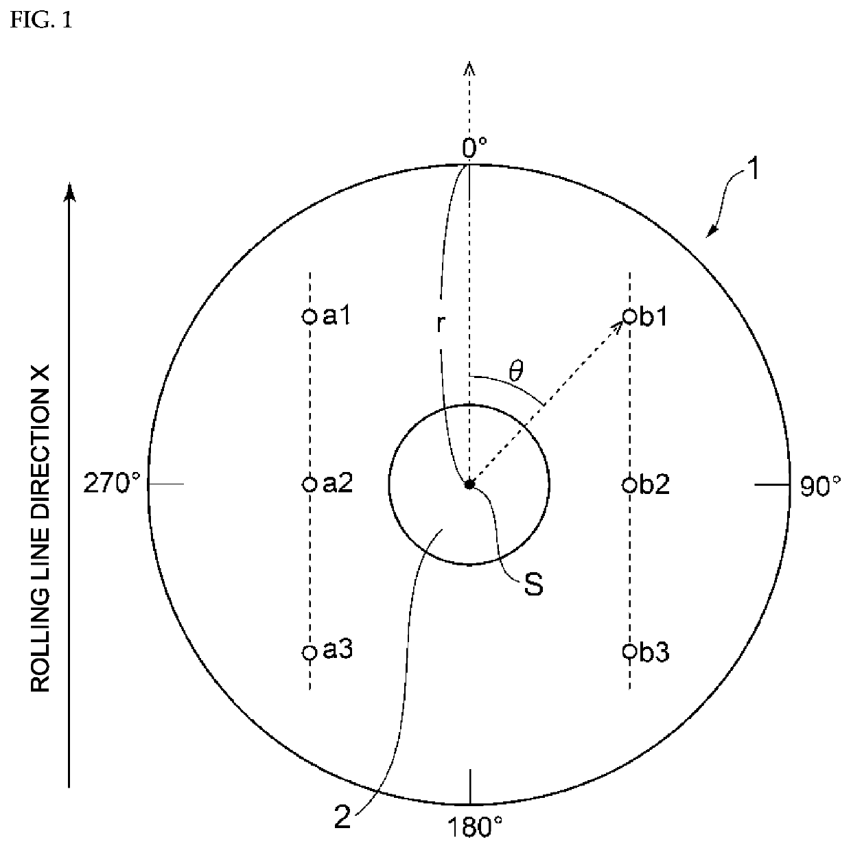
An aluminum alloy substrate (1) for magnetic disk satisfies at least two of three inequalities of an inequality group [A] and satisfies all of four inequalities of an inequality group [B], or satisfies at least two of the three inequalities of the inequality group [A] and satisfies all of four inequalities of an inequality group [C], when a plate thickness of the disk at a position (b1) is defined as tb1, a plate thickness at a position (b2) is defined as tb2, a plate thickness at a position (b3) is defined as tb3, a plate thickness at a position (a1) is defined as ta1, a plate thickness at a position (a2) is defined as ta2, and a plate thickness at a position (a3) is defined as ta3.
Description
CROSS REFERENCE TO RELATED APPLICATIONS[0001]The present application is a continuation application of International Patent Application No. PCT / JP2019 / 011410 filed on Mar. 19, 2019, which claims priority to Japanese Patent Application No. 2018-056479, filed on Mar. 23, 2018. The contents of these applications are incorporated herein by reference in their entirety.BACKGROUNDTechnical Field[0002]The present disclosure relates to an aluminum alloy substrate for magnetic disk, a disk drive device, a method for manufacturing an aluminum alloy substrate for magnetic disk, and a method for measuring an aluminum alloy substrate for magnetic disk, and particularly relates to an aluminum alloy substrate for magnetic disk that is used as a recording medium for a computer, and a method for manufacturing the aluminum alloy substrate.Description of the Related Art[0003]Conventionally, in computers, disk drive devices such as hard disk drives (hereinafter, referred to as “HDD”) have been widely use...
Claims
Login to View More Application Information
Patent Timeline
 Patent Type & Authority Applications(United States)
IPC IPC(8): G11B5/73G11B5/84
CPCG11B5/73919G11B5/8404C22F1/047C22F1/00C22C21/06G11B5/82
Inventor IMAKAWA, KIMIENAKAMURA, TOSHIHIROTAKAHASHI, HIDEKIYOSHIMURA, KEITAKUMAGAI, WATARUKITAMURA, NAOKIKITAWAKI, KOTARO
Owner FURUKAWA ELECTRIC CO LTD
Features
- R&D
- Intellectual Property
- Life Sciences
- Materials
- Tech Scout
- Unparalleled Data Quality
- Higher Quality Content
- 60% Fewer Hallucinations
Learn More Browse by: Latest US Patents, China's latest patents, Technical Efficacy Thesaurus, Application Domain, Technology Topic, Popular Technical Reports.
© 2025 PatSnap. All rights reserved.Legal|Privacy policy|Modern Slavery Act Transparency Statement|Sitemap|About US| Contact US: help@patsnap.com


