Transitional joint of pipe body

A technology of transition joints and pipe bodies, which is applied in the direction of pipes/pipe joints/pipe fittings, passing elements, sealing surface connections, etc., and can solve the problem of high cost

Active Publication Date: 2009-12-02
应永华
View PDF0 Cites 7 Cited by
  • Summary
  • Abstract
  • Description
  • Claims
  • Application Information

AI Technical Summary

Problems solved by technology

In the actual installation process, it is necessary to configure transition joints of various specifications to adapt to the connection between different pipe bodies, and the cost is relatively high

Method used


Image

  • Transitional joint of pipe body
  • Transitional joint of pipe body
  • Transitional joint of pipe body

Examples


Embodiment Construction

[0014] The present invention will be further described in detail below in conjunction with the accompanying drawings and embodiments.

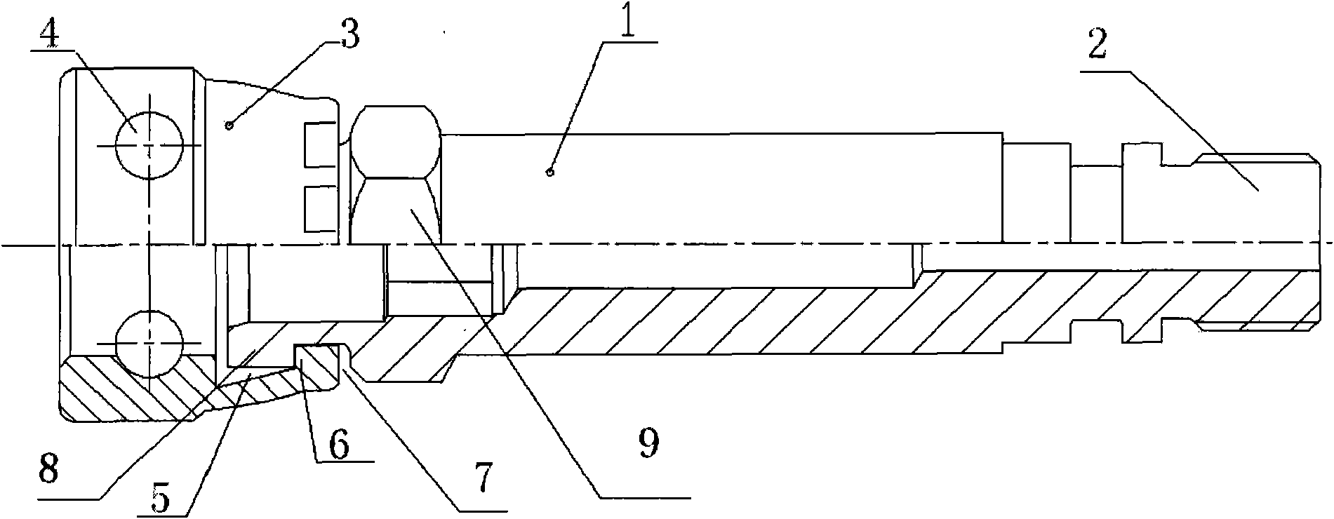
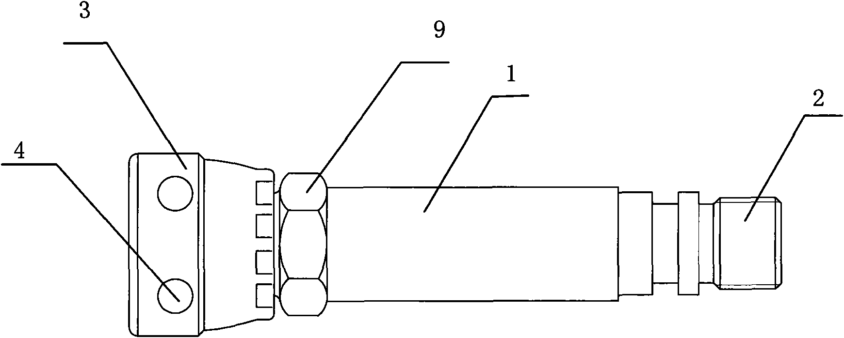
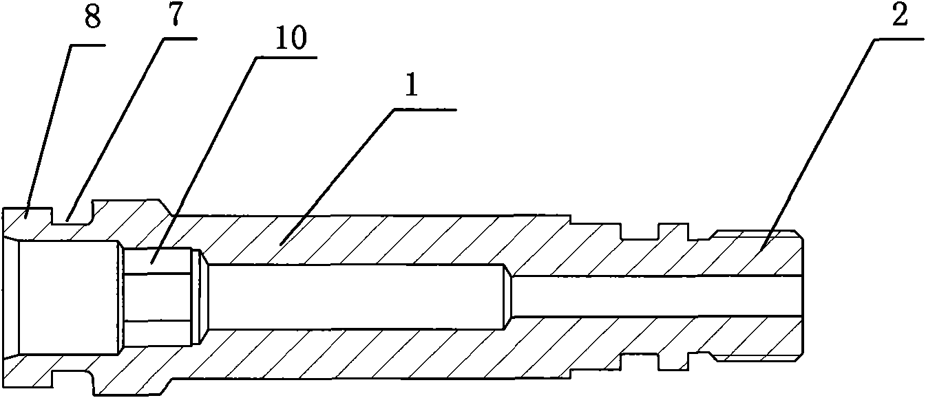
[0015] A transition joint for a pipe body, comprising a base body 1, one end of the base body 1 is fixedly provided with a joint 2 with an external thread, it also includes a ferrule 3, a U-shaped cartoon hole 4 is arranged on the ferrule 3, and the ferrule 3 includes a second A card slot 5 and a first snap ring 6, the other end of the substrate 1 is provided with a second card slot 7 and a second snap ring 8, the first card slot 5 cooperates with the second snap ring 8, the second card slot 7 cooperates with the first Snap ring 6 cooperates. The joint 2 is integrated with the base body 1 . The base body 1 is provided with an inner hexagonal hole 10 . An outer hexagonal nut 9 is fixed outside the base body 1 .


PUM


Abstract

The invention discloses a transitional joint of a pipe body, which comprises a base body and a clamping sleeve. One end of the base body is fixedly provided with a joint with outer threads; the clamping sleeve is provided with a U-shaped clamping through hole and comprises a first clamping groove and a first clamping ring; the other end of the base body is provided with a second clamping groove and a second clamping ring; the first clamping groove and the second clamping ring are matched; and the second clamping groove and the first clamping ring are matched. The transitional joint has the advantages that the clamping sleeve can rotate on the base body so as to freely adjust the position of the U-shaped clamping through hole, and the U-shaped clamping through hole completely corresponds to a through hole of the pipe body, and a U-shaped clamp can be inserted to make the clamping sleeve fixed with the connected pipe body.

Description

technical field [0001] The invention relates to a transition joint, in particular to a transition joint of a pipe body. Background technique [0002] There is a transition joint for pipes used for connection between pipes. It includes a base body. One end of the base body is provided with a joint with external threads, and the other end of the base body is provided with a ferrule. The joint, base body and ferrule are integrated For setting, the card sleeve is provided with a U-shaped cartoon hole for installing a U-shaped card. During use, after the connector with external thread is completely screwed into the pipe body, the through hole on the ferrule may not correspond to the through hole of the matching pipe body, so the U-shaped card cannot be inserted. For this reason, it is necessary to unscrew the connector of the external thread a little in reverse, so that the through hole on the ferrule completely corresponds to the through hole of the matching pipe body, and inse...

Claims


Application Information

Patent Timeline
Patent Type & Authority Applications(China)
IPC IPC(8): F16L37/113F16L19/02
Inventor 应永华何盈飞
Owner 应永华
Why Eureka
Try Eureka