Universal mould clamp

A mold clamp and template technology, which is applied in the field of general mold clamps, can solve problems such as poor adaptability, potential safety hazards, and mold clamps that cannot be used universally, and achieve the effects of convenient operation, good adaptability, and simple structure

Active Publication Date: 2015-04-01
延锋彼欧(上海)汽车外饰系统有限公司
View PDF5 Cites 2 Cited by
  • Summary
  • Abstract
  • Description
  • Claims
  • Application Information

AI Technical Summary

Problems solved by technology

There are mainly two types of existing injection molding machines, one is hydraulic fixture template injection molding machine, this type of injection molding machine needs to set mold clamps on the template to fix the mold, but the existing mold clamps cannot adjust the stroke according to the size of the mold, for example When a mold of about 1,000 tons needs to be fixed on a 2,000-3,000-ton injection molding machine for injection, the mold clamp stroke on the existing injection molding machine template cannot meet the production safety requirements of small molds, that is, the existing injection molding machine template. The mold clamps are not universal and have poor adaptability; the other is the magnetic template injection molding machine. This kind of injection molding machine does not need to set the mold clamp on the template, and can fix the mold smaller than the template by magnetic force. It has good adaptability, but there are potential safety hazards.

Method used


Image

  • Universal mould clamp
  • Universal mould clamp
  • Universal mould clamp

Examples


Embodiment Construction

[0015] The preferred embodiments of the present invention are given below in conjunction with the accompanying drawings, and described in detail, so that the functions and characteristics of the present invention can be better understood.

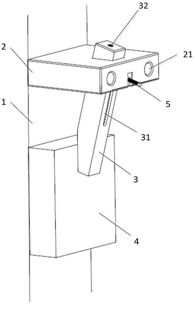
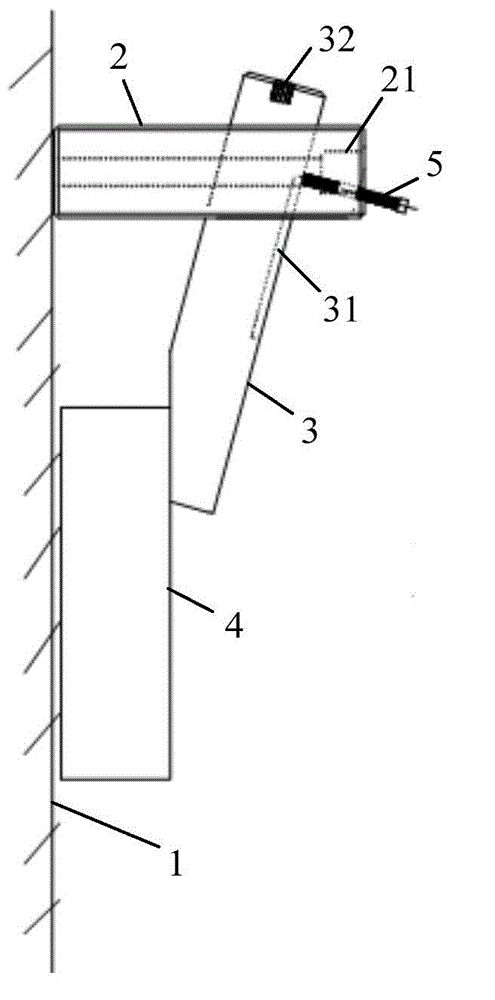
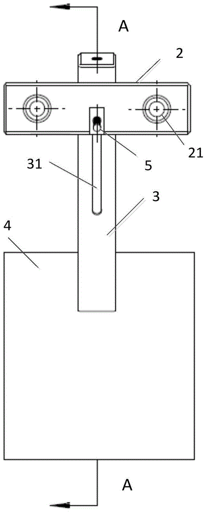
[0016] Such as Figure 1-4 As shown, the universal mold clamp of the present invention includes a fixed plate 2 vertically fixedly installed on the template 1 of the injection molding machine, and a locking column 3 extending obliquely through the center of the fixed plate 2, wherein the lock The tight column 3 is provided with a positioning groove 31 in the axial direction on the side facing away from the template 1 of the injection molding machine, and a first fastener (shown as a locking bolt 5 in the figure) extends through the fixing plate 2 and enters the positioning groove 31 to connect the locking column 3 and the fixed plate 2 together. In addition, the locking column 3 also has a pressing surface that cooperates with the contact ...


PUM


Abstract

The invention provides a universal mould clamp for fastening a mould on a molding board. The universal mould clamp comprises a fixed plate which is fixedly arranged on the molding board perpendicularly as well as a locking column which extends after penetrating through the fixing plate in an inclined manner, wherein a positioning slot is formed along the axial direction of the locking column; the locking column is fixedly connected with the fixing plate by virtue of a first fastening piece which penetrates through the fixing plate to extend into the positioning slot; and the locking column is further provided with a pressing surface which is in force fit with the mould. The universal mould clamp disclosed by the invention is simple in structure, convenient to operate, capable of being freely regulated according to the size of the mould without being limited by the size of the mould, and good in adaptation.

Description

technical field [0001] The invention relates to a mold clamp, in particular to a universal mold clamp. Background technique [0002] Injection molding refers to molding by melting plastic particles and then injecting them into the cavity of the mold. There are mainly two types of existing injection molding machines, one is hydraulic fixture template injection molding machine, this type of injection molding machine needs to set mold clamps on the template to fix the mold, but the existing mold clamps cannot adjust the stroke according to the size of the mold, for example When a mold of about 1,000 tons needs to be fixed on a 2,000-3,000-ton injection molding machine for injection, the mold clamp stroke on the existing injection molding machine template cannot meet the production safety requirements of small molds, that is, the existing injection molding machine template. Mold clamps are not universal and have poor adaptability; the other is magnetic template injection moldin...

Claims


Application Information

Patent Timeline
Patent Type & Authority Applications(China)
IPC IPC(8): B29C45/17B29C33/30
CPCB29C33/307
Inventor 陈爱军卓铁武陈宜江
Owner 延锋彼欧(上海)汽车外饰系统有限公司
Why Eureka
Try Eureka