Workpiece demagnetizing method and workpiece demagnetizing device

A degaussing method and a technology of a degaussing device, which are applied in the field of degaussing, can solve problems such as unsatisfactory degaussing effect and failure to be used in real applications, and achieve the effects of good degaussing effect, compact structure, and reduced device volume

Inactive Publication Date: 2009-12-02
HUAIYIN INSTITUTE OF TECHNOLOGY
View PDF0 Cites 13 Cited by
  • Summary
  • Abstract
  • Description
  • Claims
  • Application Information

AI Technical Summary

Problems solved by technology

But the degaussing method disclosed by it is still traditional; the technical scheme of the degaussing device is not complete, and its degaussing effect is not ideal as far as it is known, so it has not been really applied in practice.

Method used


Image

  • Workpiece demagnetizing method and workpiece demagnetizing device
  • Workpiece demagnetizing method and workpiece demagnetizing device
  • Workpiece demagnetizing method and workpiece demagnetizing device

Examples


example 1

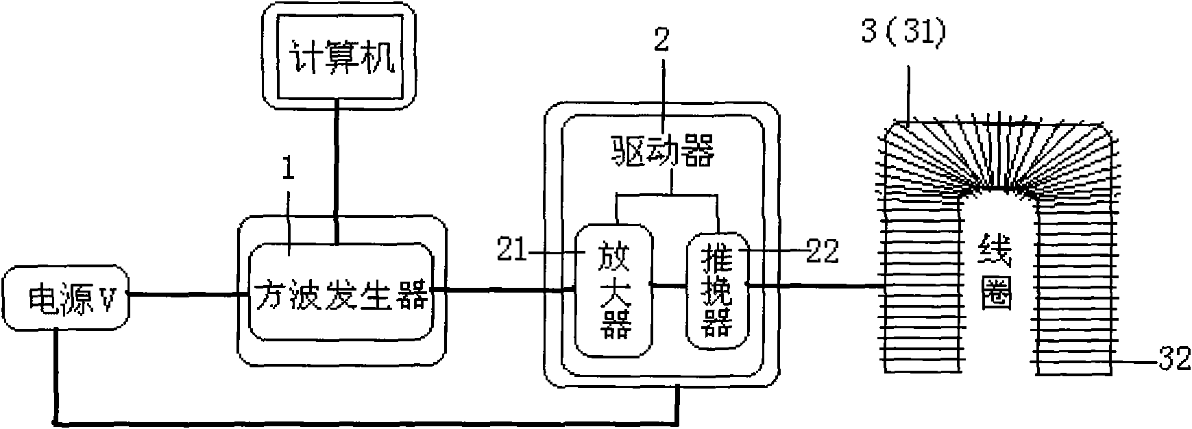
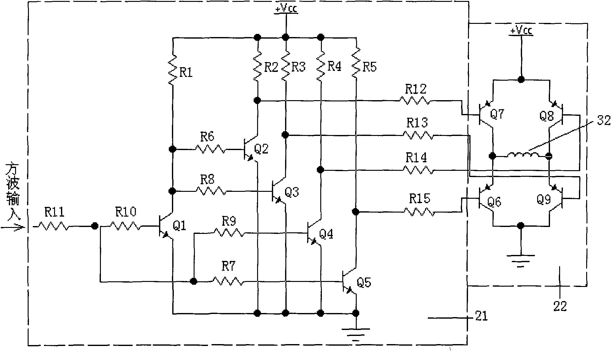
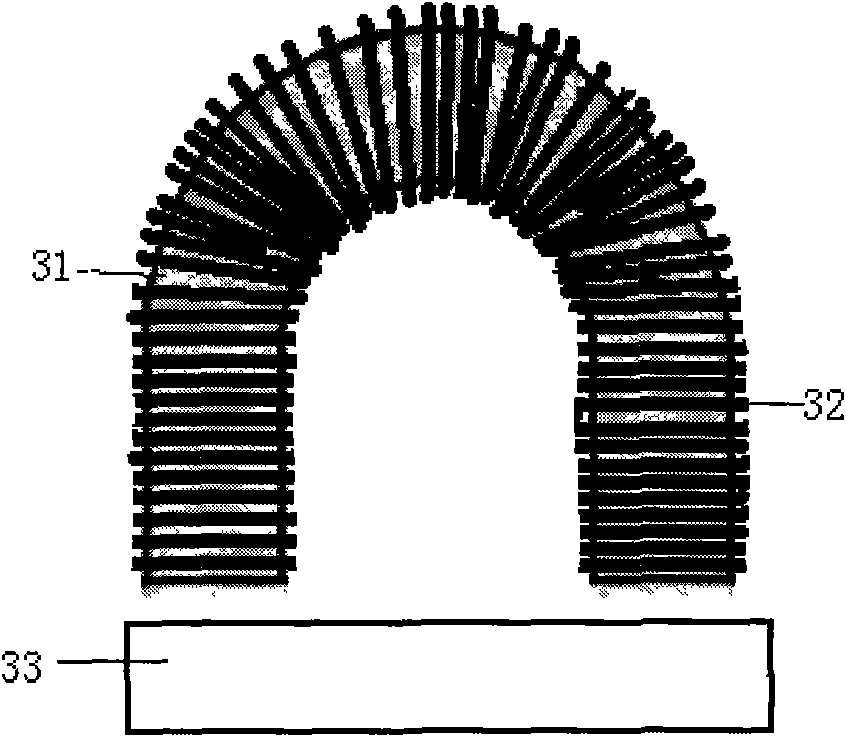
[0031] After testing, the residual magnetism in a certain section of the workpiece is 100Gs, and the relative movement speed of the workpiece is 1.5m / s. The design degaussing magnetic field is 300Gs, the square wave frequency is 600Hz, and the power supply is 24V DC; ferrite selection: the initial permeability is greater than 2200, the shape is a large semi-circular ring, the cross-section is 10mm×20mm, and the effective degaussing area is 20mm×30mm; coil The copper wire diameter is selected as 0.56mm, and the number of turns is 320 turns. After degaussing, the residual magnetism of this section of the workpiece is less than 1Gs after testing.

example 2

[0033] After testing, the residual magnetism in a certain section of the workpiece is 200Gs, and the relative movement speed of the workpiece is 1.5m / s. The design degaussing magnetic field is 300Gs, the square wave frequency is 600Hz, and the power supply is 24V DC; ferrite selection: the initial permeability is greater than 2200, the shape is a large semi-circular ring, the cross-section is 10mm×20mm, and the effective degaussing area is 20mm×30mm; coil The copper wire diameter is selected as 0.56mm, and the number of turns is 320 turns.

[0034] After degaussing, the residual magnetism of this section of the workpiece is less than 1Gs after testing.

example 3

[0036] After testing, the residual magnetism of a section of the workpiece is 800Gs, and the relative movement speed of the workpiece is 1.2m / s. The design degaussing magnetic field is 2000Gs, the square wave frequency is 400Hz, and the power supply is 60V DC; ferrite selection: the initial permeability is greater than 2200, the shape is U-shaped, the cross-section is 30mm×70mm, and the effective degaussing area is 70mm×80mm; coil selection The diameter of the copper wire is 1.40 mm, and the number of turns is 860 turns.

[0037] After degaussing, the residual magnetism detected in this section of the workpiece is less than 1Gs.


PUM


Abstract

The invention relates to a workpiece demagnetizing method and a workpiece demagnetizing device. The method selects a square wave signal with unchanged frequency and amplitude; an amplifying circuit and a push-pull circuit are connected into a drive circuit; and the drive circuit is connected with a coil. Corresponding to the method, the demagnetizing device mainly comprises a power supply, a signal generator, a driver and a coil. An unfading alternating magnetic field generated by the method and the device can not only demagnetize a static workpiece but also can carry out continuous demagnetization on a dynamic workpiece and have wide application range; a ferrite is adopted as a magnetic core; demagnetizing current with high frequency and unchanged amplitude is conducted to the coil; the alternating magnetic field generated by the coil can disturb the residual magnetic domain of the workpiece; the demagnetizing effect is good; and the method is simple and feasible and the device has a compact structure so as to solve the difficult problem of demagnetization in the field and have practical value.

Description

technical field [0001] The invention relates to degaussing technology, in particular to a degaussing method and a degaussing device for workpieces. Background technique [0002] In industrial production, due to the process conditions, there is often residual magnetism on the workpiece. When the residual magnetism exceeds a certain value, it will cause misjudgment during workpiece flaw detection, so the workpiece must be demagnetized; however, sometimes Due to the needs of workpiece flaw detection, it is necessary to smear magnetic powder on the surface of the workpiece for comparison test to assist in the judgment of flaw detection, but eventually the residual magnetism on the workpiece must be eliminated. At this stage, foreign degaussing methods for workpieces mainly use alternating power supply and supply power frequency current of appropriate strength to the coil, so that the alternating magnetic field generated by the coil acts on the residual magnetic area of ​​the wor...

Claims


Application Information

Patent Timeline
Patent Type & Authority Applications(China)
IPC IPC(8): H01F13/00
Inventor 胡光张俊吴一清
Owner HUAIYIN INSTITUTE OF TECHNOLOGY
Why Eureka
Try Eureka