
Automatically controlled direct current degaussing device and method

A technology of DC degaussing and degaussing method, applied in the field of degaussing, which can solve the problems of inconvenient carrying and transportation, difficulty in meeting steel plate welding requirements, inability to degauss large flat plates, etc., and achieve good degaussing effect

Pending Publication Date: 2022-01-11
CENT IRON & STEEL RES INST +1
View PDF1 Cites 0 Cited by
  • Summary
  • Abstract
  • Description
  • Claims
  • Application Information

AI Technical Summary

Problems solved by technology

For example, Chinese utility model patent ZL200920147276.7 proposes "a degaussing device for workpieces". connected to generate an alternating magnetic field. This device mainly uses AC magnetic field degaussing, which is suitable for steel plates with small coercive force. When the coercive force is greater than 100Gs, AC demagnetization is difficult, and it is difficult to meet the actual steel plate welding requirements. Usually, the steel plate needs to be It is placed in the coil of the device, resulting in a large volume and complex structure, which is inconvenient to carry and carry, and is not suitable for field construction. At the same time, the size of the demagnetized parts is affected by the internal space of the degaussing equipment, so it cannot be used for large-scale welding after on-site welding. Degaussing the tablet

Method used


Image

  • Automatically controlled direct current degaussing device and method

Examples


Embodiment Construction

[0028] The present invention will be further described below in conjunction with the embodiments and the accompanying drawings.

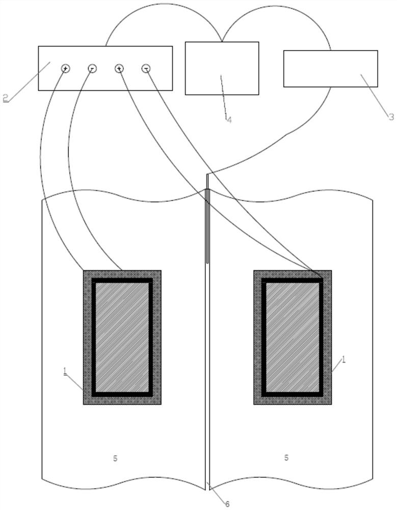
[0029] The present invention is an automatic control DC degaussing device, which comprises a degaussing head 1 , a program-controlled power supply 2 , a Gauss meter 3 and a PLC controller 4 . The degaussing heads 1 are generally two in a pair, used at the same time, placed on both sides of the weld 6 of the large steel plate 5 to be welded, used to generate a DC strong magnetic field to offset the magnetic field at the weld of the large steel plate, the degaussing head 1 and the program-controlled power supply 2 positive and negative connections. On the one hand, the program-controlled power supply is connected to the degaussing head, outputs DC current, and supplies power to the degaussing head to generate the required DC magnetic field; The PLC controller 4 is the control system of the device, which has a well-prepared setting program inside, and...


PUM

PropertyMeasurementUnit
lengthaaaaaaaaaa

Abstract

The invention belongs to the technical field of degaussing, and relates to an automatically controlled direct current degaussing device and method for eliminating a welding seam magnetic field in the butt welding process of large steel plates in the industrial production. In the degaussing device, a pair of degaussing heads (1) are movably arranged at the front end of a welding machine, are symmetrically arranged at the two sides of a to-be-welded edge seam, and are connected with a positive electrode and a negative electrode of a programmable power supply (2), and the programmable power supply (2) supplies power through commercial power, so that a direct-current strong magnetic field is generated between the two demagnetizing heads (1). A Gauss meter (3) is connected with a PLC (4) through a serial port and is used for collecting the magnetic field data of the to-be-welded edge seam and transmitting the magnetic field data to the PLC (4), the PLC (4) controls the programmable power supply (2) to output a current through the program operation to enable the demagnetizing heads (1) to generate a needed demagnetizing magnetic field, the magnetic field of the welding seam (6) of a steel plate (5) is counteracted before welding, and therefore it is guaranteed that the magnetic field at the welding seam of the large steel plate meets the set requirement. The degaussing device is easy to operate and is suitable for the automatic control over the magnetic field in the large steel plate butt welding process.

Description

technical field [0001] The invention belongs to the technical field of degaussing, and in particular relates to an automatic control DC degaussing device and method for eliminating the strong magnetic field of butt weld seams of large steel plates in the industrial welding process. Background technique [0002] In the process of steel plate processing and welding, because the steel plate will inevitably be exposed to large current and magnetic field, resulting in a certain residual magnetic field on the surface of the steel plate, when the size of the steel plate is large or the steel plate is exposed to a strong magnetic field, the weld Stitching will generate a strong magnetic field of more than 50Gs, which may reach 200-300Gs in actual working conditions, causing the welding arc to shift, affecting the welding quality, and thus affecting the welding of large-scale steel plates. Existing degaussing devices mainly use an alternating magnetic field to continuously change the...

Claims


Application Information

Patent Timeline
Patent Type & Authority Applications(China)
IPC IPC(8): H01F13/00
CPCH01F13/006
Inventor 杨锋李冉胡健朱弢谢章龙吴俊平席连云刘通
Owner CENT IRON & STEEL RES INST
Learn More