
LED bulb

A technology of LED light bulbs and LED light sources, which is applied in cooling/heating devices of lighting devices, lighting and heating equipment, semiconductor devices of light-emitting elements, etc., and can solve problems such as opacity, poor luminous effect, and complex structure

Inactive Publication Date: 2009-12-09
SMALUX ELECTRICAL MFG
View PDF0 Cites 22 Cited by
  • Summary
  • Abstract
  • Description
  • Claims
  • Application Information

AI Technical Summary

Problems solved by technology

Fluorescent light bulbs appeared after incandescent light bulbs. Although they are energy-saving and brighter, they are not environmentally friendly due to the large amount of fluorescent powder used.
At present, more energy-saving and environmentally friendly LED light sources have emerged, and LED bulbs have been produced. The existing LED bulbs generally have complex structures, mainly including three parts-lamp caps, necks, and luminous spherical surfaces. The lamp caps are all standard parts, and the neck Generally, there are two kinds of materials: plastic and metal. The neck is generally opaque and is mainly used for connection and heat dissipation or placing the driver. The luminous spherical surface is generally made of plastic and glass for light transmission, and generally requires additional heat dissipation. The cooling device is generally visible from the outside and has a weird shape, so its shape and internal structure are quite different from ordinary incandescent bulbs
[0003] In the existing LED light bulbs, the light emitting direction of the LED is generally forward. Due to the limitation of the light emitting angle of the LED, the light of the existing LED light bulbs has a taper angle, which cannot be directed in the same direction as the traditional incandescent light bulbs and fluorescent light bulbs. glow in all directions
After using LED bulbs to replace incandescent bulbs and fluorescent bulbs and put them into the lamps, due to the difference in luminous mode, the luminous effect will be quite different from that of incandescent bulbs and fluorescent bulbs, which cannot achieve the luminous effect of lamp design, and the decorative performance is great discounted, thus adversely affecting bulb replacement
In addition, in order to meet the requirement of high brightness, the existing LED light bulbs need to install a large number of LEDs. Since the space inside the light bulb is small, in order to save space, LEDs are generally stacked and arranged in dislocations, and each LED will be interfered with each other when emitting light. Refraction and reflection occur, which in turn leads to poor light transmission and poor luminous effect

Method used


Image

  • LED bulb
  • LED bulb
  • LED bulb

Examples


Embodiment 1

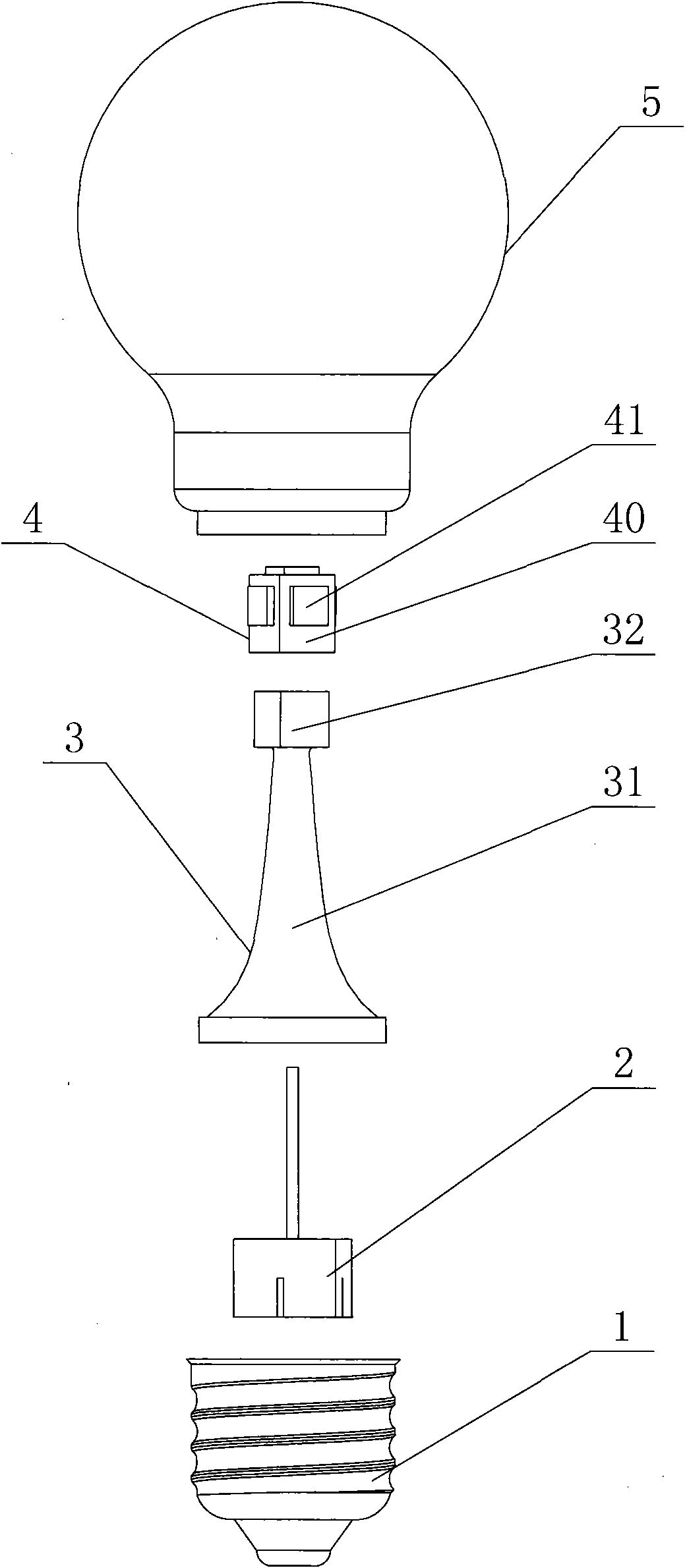
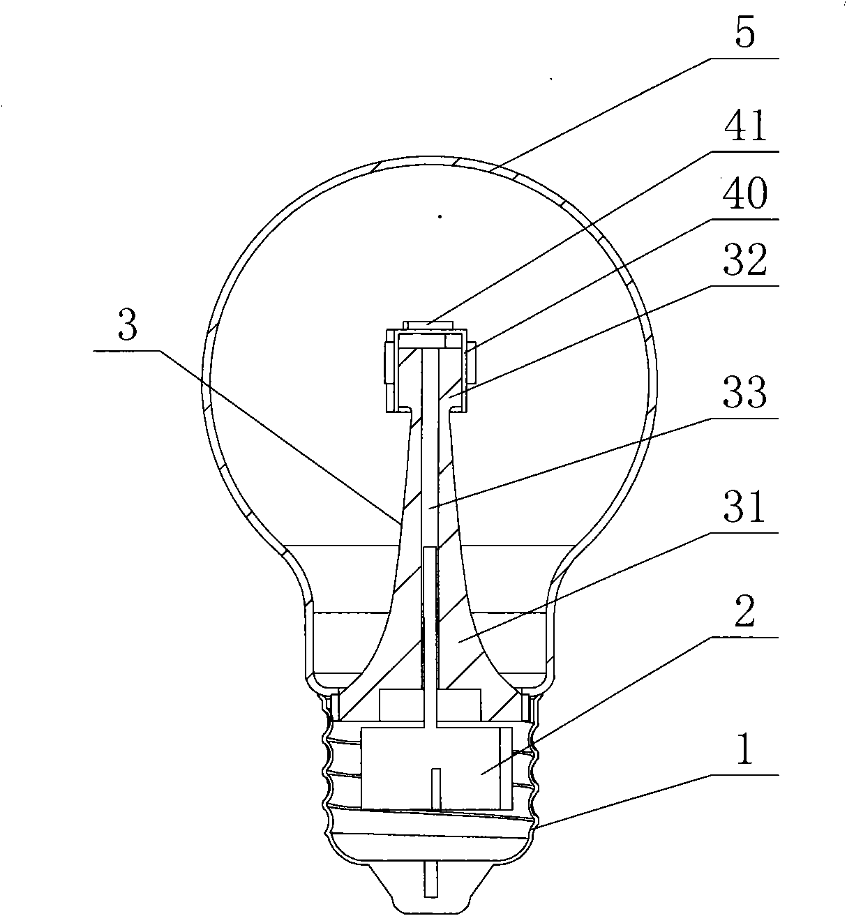
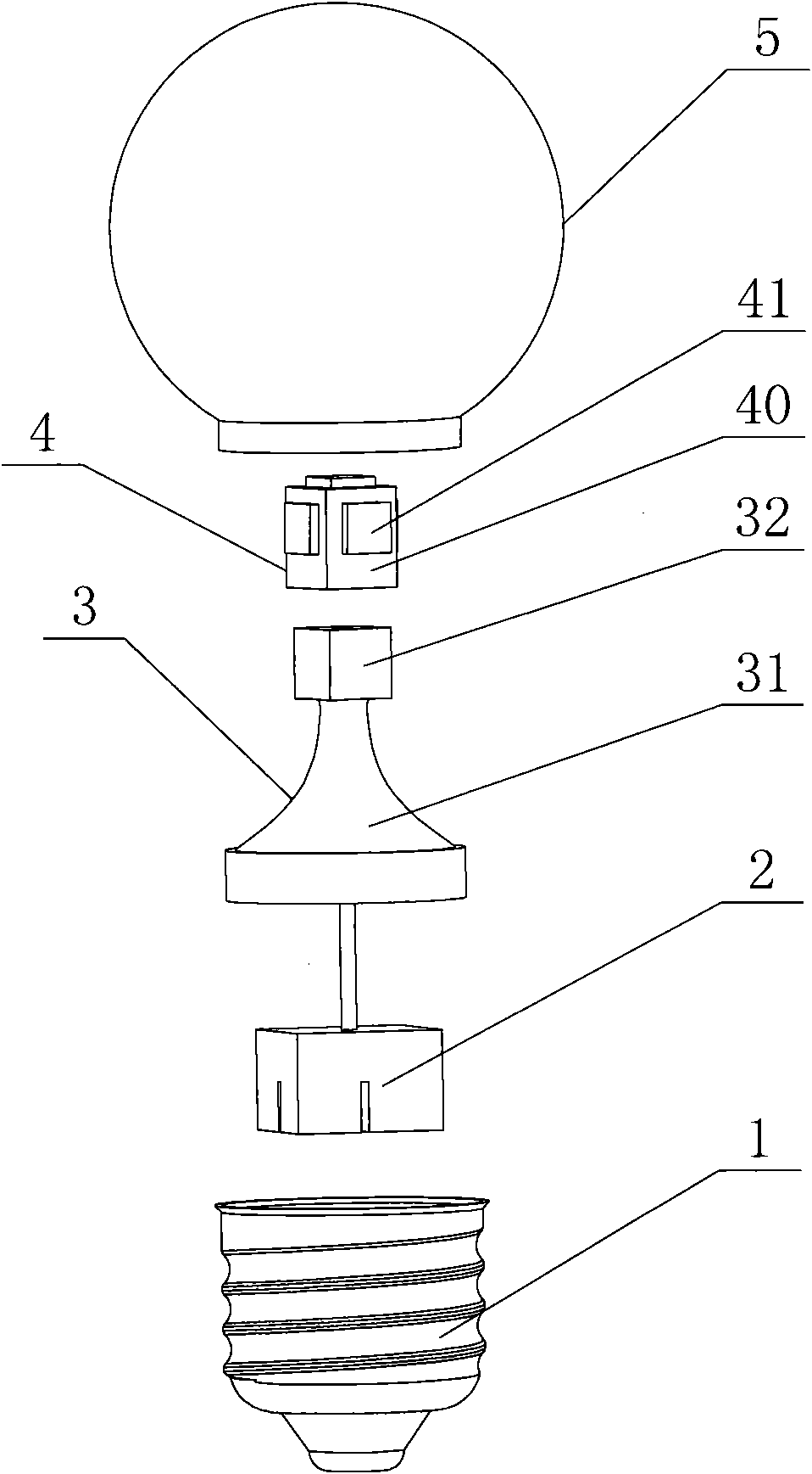
[0029] Such as figure 1 , figure 2 As shown, the LED light bulb of this embodiment includes a lamp cap 1, a drive circuit assembly 2, a light source bracket 3, an LED light source 4, and a bulb shell 5. The bulb shell 5 is pear-shaped, and the tail of the bulb shell 5 is connected to the lamp cap. 1 phase is fixedly connected, the drive circuit assembly 2 is located in the lamp holder 1, the bulb 5 surrounds the LED light source 4 and the light source bracket 3 in the inner cavity, and the model of the lamp holder 1 is E27, of course It can also be other models such as E26 or E14 or E12 or GU10 or GU5.3 or B22. The bulb shell 5 is made of plastic and has an integrated structure. Of course, it can also be made of glass. The bulb shell 5 is completely transparent. It can also be partly transparent. The light source support 3 includes a base 31 and a polyhedron 32. The light source support 3 is made of aluminum, which has a good appearance and good thermal conductivity. Of cour...

Embodiment 2

[0031] Such as image 3 , Figure 4As shown, the difference between the present embodiment and the first embodiment is that: the bulb 5 of the present embodiment is spherical and has a smaller volume, which is the same as the shape of an existing incandescent light bulb with less power.

[0032] The remaining features of this embodiment are the same as those of Embodiment 1.

Embodiment 3

[0034] Such as Figure 5 , Figure 6 As shown, the difference between the present embodiment and the first embodiment is that the bulb shell 5 of the present embodiment is in the shape of a candle, which is the same as the shape of the existing elongated candle light bulb.

[0035] The remaining features of this embodiment are the same as those of Embodiment 1.


PUM


Abstract

The invention discloses an LED bulb, which has good light transmitting performance and has the same light emitting mode, volume and shape as common incandescent light bulbs. The LED bulb comprises a bulb holder (1), a driving circuit component (2), a light source support (3), an LED light source (4) and a bulb case (5), wherein the light source support (3) comprises a pedestal (31) and a polyhedron (32) and is made of metal; the internal axial center of the pedestal (31) is provided with a wire hole (33); the polyhedron (32) is positioned on the top of the pedestal (31); the lower part of the pedestal (31) and the inner wall of the bulb holder (1) are contacted tightly for heat conduction; the LED light source (4) comprises heat dissipating baseplates (40) and LED chips (41) positioned on the heat dissipating baseplates (40); the heat dissipating baseplates (40) are directly fixed on each surface of the polyhedron (32) in the circumferential direction, and the LED chips (41) give out light in all directions by taking surfaces of the polyhedron (32) in the circumferential direction as the reference surfaces; and the driving circuit component (2) is electrically connected with the bulb holder (1) and the LED light source (4) through leads.

Description

technical field [0001] The invention relates to an LED light bulb. Background technique [0002] Traditional light bulbs are incandescent light bulbs with low illuminance, dim light and no energy saving. After the incandescent light bulb, the fluorescent light bulb appeared. Although it is energy-saving and bright, it is not environmentally friendly due to the large amount of fluorescent powder used. At present, more energy-saving and environmentally friendly LED light sources have emerged, and LED bulbs have been produced. The existing LED bulbs generally have complex structures, mainly including three parts-lamp caps, necks, and luminous spherical surfaces. The lamp caps are all standard parts, and the neck Generally, there are two kinds of materials: plastic and metal. The neck is generally opaque and is mainly used for connection and heat dissipation or placing the driver. The luminous spherical surface is generally made of plastic and glass for light transmission, and ...

Claims


Application Information

Patent Timeline
Patent Type & Authority Applications(China)
IPC IPC(8): F21S2/00F21V17/00F21V19/00F21V23/00F21V29/00F21Y101/02F21K9/232F21V29/50F21Y115/10
Inventor 张夙敏
Owner SMALUX ELECTRICAL MFG
Learn More