Device for measuring the volume or mass flow rate of a medium in a pipe

A volume flow, mass flow technology, applied in the field of measuring tubes, can solve problems such as short circuit, flow meter damage, failure, etc., achieve high chemical stability, reduce manufacturing costs, and excellent high temperature resistance

Inactive Publication Date: 2009-12-09
ENDRESS HAUSER FLOWTEC AG
View PDF1 Cites 4 Cited by
  • Summary
  • Abstract
  • Description
  • Claims
  • Application Information

AI Technical Summary

Problems solved by technology

In extreme cases, this can lead to short circuits in the area of ​​the measuring electrodes and thus to malfunctions, or even complete destruction of the flowmeter

Method used


Image

  • Device for measuring the volume or mass flow rate of a medium in a pipe
  • Device for measuring the volume or mass flow rate of a medium in a pipe
  • Device for measuring the volume or mass flow rate of a medium in a pipe

Examples


Embodiment Construction

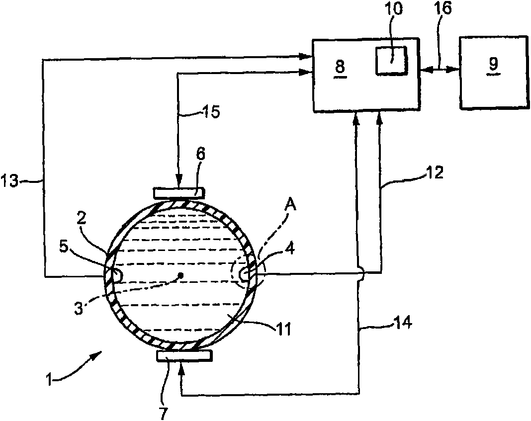
[0029] figure 1 is a schematic diagram of the magnetic induction flowmeter 1 . The medium 11 flows through the measuring tube 2 according to the invention in the direction of the measuring tube axis 3 . The medium 11 is at least slightly conductive.

[0030] The measuring tube 2 is lined on its inner surface 30 with a liner 18 . The lining 18 consists of a non-conductive material which is highly chemically and / or mechanically stable. The liner 18 is preferably made of a plastic approved for potable water applications. In this way, the flow meter 1 can be widely used in different applications.

[0031] A magnetic field B perpendicular to the flow direction of the medium 11 is generated by a magnet system, ie, for example by two diametrically opposite coil arrangements 6 , 7 or by two electromagnets. Under the influence of the magnetic field B, the charge carriers located in the medium 11 are each migrated, depending on the polarity, to the two measuring electrodes 4 , 5 of...


PUM

PropertyMeasurementUnit
thicknessaaaaaaaaaa

Abstract

The invention relates to a measuring tube (2) for any flow meter (1) that determines or monitors the volume or mass flow rate of a medium (11) flowing in a pipe (33). A powder-coatable plastic is applied as a primer (17), liner (18), or protective layer (28) for a liner (18) at least in the area of the internal surface of the measuring tube (2) through which the medium (11) flows.

Description

technical field [0001] The invention relates to a measuring tube for a flow meter which determines or monitors the volume flow or mass flow of a medium flowing in a pipe. Background technique [0002] Flow meters work on a variety of physical principles. In the case of known in-line flow meters, the measuring tube is inserted via two end-located fastening devices into the pipe through which the medium flows. There are, for example, magnetic induction flowmeters, ultrasonic flowmeters, vortex flowmeters, Criolis flowmeters or differential pressure measuring instruments available from the applicant. [0003] Magnetic-inductive flowmeters use the principle of electromagnetic induction for measuring the volumetric flow: Charge carriers of the medium moving perpendicular to the magnetic field induce a measuring voltage in measuring electrodes which are likewise arranged essentially perpendicular to the direction of flow of the medium. The measuring voltage induced in the measur...

Claims


Application Information

Patent Timeline
Patent Type & Authority Applications(China)
IPC IPC(8): G01F1/58F16L58/10
CPCG01F15/14F16L58/1027F16L58/1045G01F1/584
Inventor 亚历山大·斯顿齐托马斯·祖尔策
Owner ENDRESS HAUSER FLOWTEC AG
Why Eureka
Try Eureka